Procedures described in this chapter
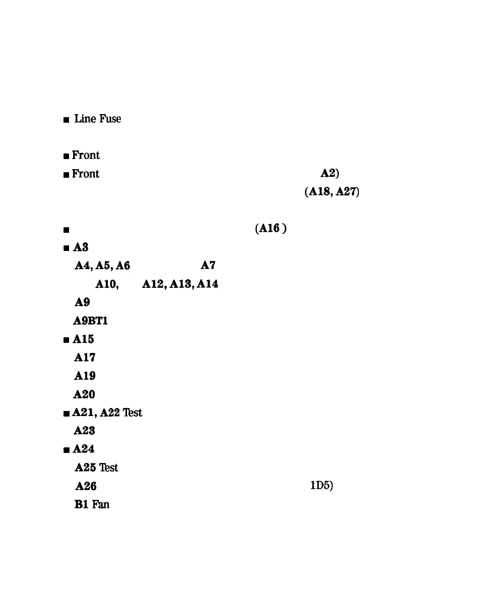
The following pages describe assembly replacement procedures for the
HP 8753E assemblies listed below:
w
LineFuse
n
Covers
w
Front
Panel Assembly
w
Front
Panel Interface and Keypad Assemblies
(Al,
A2)
n
Display, Display Lamp, and Inverter Assemblies
(Al&
A27)
n
Rear Panel Assembly
w
Rear Panel Interface Board Assembly
(Al6
)
N
A3
Source Assembly
n
A4,
A5,
A6
Samplers and
A7
Pulse Generator
n
AS,
AlO,
All,
A12,
A13,
Al4
Card Cage Boards
n
A9
CPU/PIG Board
n
A9BTl
Battery
w
Al5
Preregulator
n
Al7
Motherboard Assembly
n
A19
Graphics Processor
n
A20
Disk Drive
w
A21,
A22
Test
Port Couplers
n
A23
LED Board
w
A24
Transfer Switch
n
A25
Test
Set Interface
n
A26
High Stability Frequency Reference (Option
lD5)
n
BlFhn
Assembly Replacement and Post-Repair Procedures
14-3
 Loading...


