2 Available/Secondary Interrupt Controller
3 Serial Communications Port (COM2)
4 Serial Communications Port (COM1)
5 Parallel Communications Port (LPT1)
6 Standard Floppy Disk Controller
lowest 7 Parallel Communications Port (LPT2)
The combination of the separate, prioritized, interrupt request lines and the operation of the
8259A controller chip allows the CPU to ignore at least temporarily some relatively unimportant
interrupts so that it can process more important ones instead. In addition, a programmer can
ensure that the CPU ignores even the interrupt requests that the 8259A sends. The FLAGS
register includes an "interrupt enable" bit. If this bit is zero, the CPU will ignore any incoming
device interrupts and we say that interrupts are disabled. If the bit is one, interrupts are enabled
and the CPU will process the interrupt. The CLI (clear interrupt flag) and STI (set interrupt flag)
instructions give programmers control over when the CPU should ignore interrupts.
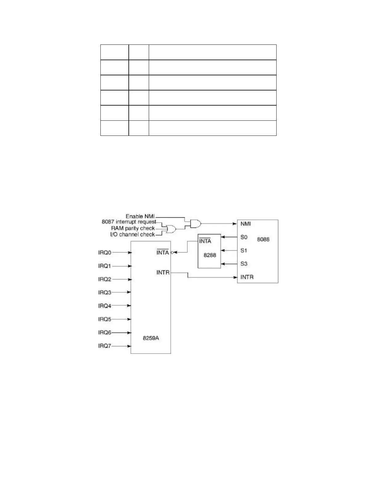
8259A Interrupt Controller ("IBM BIOS Technical Reference", 1984, IBM Corp.)
The interrupt flag in the FLAGs register gives programmers the option of enabling or disabling
all interrupts. Often this is sufficient, but in other cases, the programmer may need to disable
only certain interrupts. The 8259A chip has an 8-bit internal register called the IMR (interrupt
mask register). Each bit in the register corresponds to one of the interrupt request levels. If bit n
in the mask is zero, IRQ line n is disabled.
In addition to the eight input lines of the 8259A controller, the microprocessor has one other
input line for interrupts. This is the NMI (NonMaskable Interrupt) line. As you can see in the