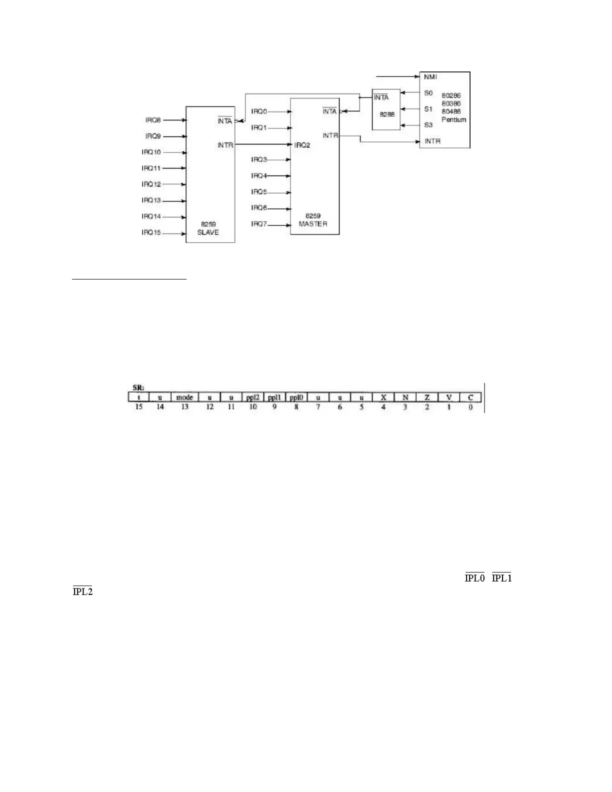
Cascaded Interrupt Controllers ("IBM BIOS Technical Reference", 1984, IBM Corp.)
Motorola 680x0 Family
The Motorola family uses some of the same general concepts that we have seen with the Intel
family, but interrupt prioritization and recognition also includes some important differences. The
Motorola chips have a status register (SR) that corresponds in many ways to the Intel FLAGS
register. One important difference is that, instead of having a single "interrupt flag" bit, the SR
includes a set of three bits. These are the "PPL" bits, PPL0, PPL1 and PPL2, where PPL is an
abbreviation for "Processor Priority Level."
Motorola 68000 Status Register
These three bits determine how important an interrupt must be before the CPU will attend to it.
This allows the CPU to ignore at least temporarily some relatively unimportant interrupts so that
it can process more important ones instead. Each type of peripheral device has an assigned
priority level (encoded with a number between 1 and 7). In general, the priority level of an
interrupt must be greater than the value in the interrupt mask before the CPU will process it.
Thus, if the value of the interrupt mask is 0, all interrupts are "enabled". In other words, no
matter what the priority level of an interrupt is, the CPU will recognize it. On the other hand, if
the value of the interrupt mask is 7, we say that interrupts are "disabled", meaning that the CPU
will process (almost) no interrupt.
These three bits correspond to three signal lines (wires) on the control bus, called , and
, where IPL is an abbreviation for "Interrupt Priority Level." These lines bear incoming
signals (high or low voltages) from a priority encoder. This encoder is a hardware device that
receives signals from up to seven different external devices. The encoder selects the highest
numbered incoming signal (just as with the Intel processor, devices may be requesting an
interrupt on more than one line). It then encodes the number of the selected signal as a 3-bit
binary number and outputs this number on the three IPL lines. In general, whenever the priority
encoder outputs a number that is greater than the current value of the interrupt mask, the CPU
will service the interrupt.