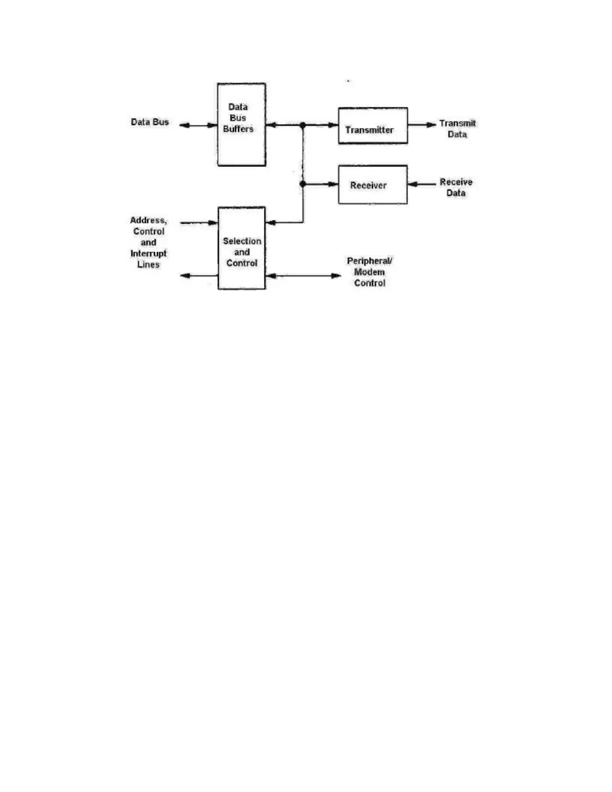
Block Diagram of the ACIA (from Motorola MC6850 data sheet)
The ACIA has four onboard registers (ports):
1. the Transmit Data Register (TDR), which is a buffer for data that the ACIA must transmit
2. the Receive data register (RDR), which is a buffer for data that the ACIA is receiving
3. the 8-bit Control register (CR), which is a write-only register that the CPU uses to direct
the permitted actions of the interface*
4. 8-bit Status register (SR), which is a read-only register that the CPU uses to determine the
current status of the interface*
* write-only and read-only are always from the point of view of the CPU
Since the device both receives and transmits data, as programmers, we must solve the problem of
determining what sort of service the device is requesting when an interrupt occurs. The interrupt
service routine must use the control and status registers as a means of both controlling what we
want to allow the device to do and of determining the meaning of an interrupt issuing from the
ACIA. This will allow the interrupt service routine to determine what actions to perform. The
bits of these registers have particular meanings and, when taken collectively, give all the
information necessary for the ISR to perform the correct actions. The meanings of the bits appear
below.
CR: CR0-CR1 used to reset the device to its start-up state (among other purposes)
CR2-CR4 used to select the word length (7 or 8-bits), parity (odd or even) and stop bits
(1 or 2)
CR5-CR6 used as transmitter control bits. Via these bits, the CPU can either enable or
disable transmit interrupts
CR7 used as a receive control bit. Via this bit, the CPU can either enable or disable
receive interrupts
SR: SR0 (RDRF) Receive Data Register Full--cleared when CPU reads data from the RDR
SR1 (TDRE) Transmit Data Register Empty (that is, it is ready to send more data)--cleared
when the CPU writes data written into the TDR
SR2 (DCD) Data Carrier Detect--set when there is no carrier (that is, the device is