Table 7: SRX650 Services Gateway Front Panel Components (continued)
DescriptionLocationComponentNumber
The SRE/ACE 1.0 LED has the
following indicator colors:
•
Green and steadily on indicates:
•
SRE1 is functioning normally.
•
ACE 1.0 half slot is functioning
normally.
•
ACE 1 full slot is functioning
normally.
•
Amber and steadily on indicates
SRE1/ACE1 (full slot) or ACE 1.0
(half slot) is initializing, performing
diagnostics, or going down.
•
Red and on steadily indicates
SRE1/ACE1 (full slot) or ACE 1.0
(half slot) failure.
•
Off indicates SRE/ACE1 slot is
empty.
NOTE: ACE modules will be
supported in a future release.
Left side of the
front chassis panel
SRE/ACE LED 1.04
For personal safety, while working on
the services gateway, use the ESD
outlet to plug in an ESD grounding
strap to prevent your body from
sending static charges to the services
gateway.
Left side of the
front chassis panel
Electrostatic discharge
(ESD) outlet
5
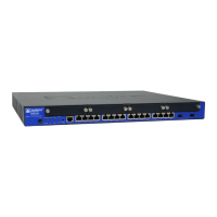
The Gigabit Ethernet ports have the
following characteristics:
•
Use an RJ-45 connector.
•
Operate in full-duplex and
half-duplex modes.
•
Support flow control.
•
Support autonegotiation.
The Gigabit Ethernet ports can be
used to:
•
Function as front-end network
ports.
•
Provide LAN and WAN
connectivity to hubs, switches,
local servers, and workstations.
•
Forwardincoming data packets to
the services gateway.
•
Receive outgoing data packets
from the services gateway.
Left side of the
front chassis panel
4 fixed Gigabit Ethernet
ports:
•
labeled Port 0/0
•
labeled Port 0/1
•
labeled Port 0/2
•
labeled Port 0/3
Provides link speeds of
10/100/1000 Mbps.
6
Copyright © 2018, Juniper Networks, Inc.20
SRX650 Services Gateway Hardware Guide