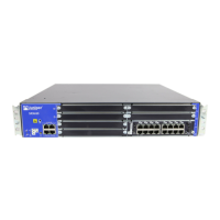
Table 7: SRX650 Services Gateway Front Panel Components (continued)
DescriptionLocationComponentNumber
•
All slots support GPIMs.
•
Slots 2 and 6 support XPIMs.
•
Slots 5 and 7 support SATA
High-Disk (RAID).
•
Slots 2, 4, 6, and 8 support PoE.
For more information about PoE,
see “SRX650 Services Gateway
Power over Ethernet Overview” on
page 8.
NOTE: GPIMs/XPIMs are
hot-swappable.
Left side of the
front chassis panel
8 GPIM slots:
•
GPIM slots 1 through
4 are located at the
first 1U high position
starting from the left
bottom of the
chassis.
•
GPIM slots 5 through
8 are located at the
second 1U high
position starting
from the left middle
of the chassis. For
specific GPIM/XPIM
slots, see
Figure 3 on page 18.
7
The POWER LED has the following
indicator colors:
•
Green and steadily on indicates
that the services gateway is
functioning normally and that the
services gateway and all power
supply units (PSUs) are receiving
power.
•
Red and steadily on indicates that
at least one PSU has failed.
•
Amber and steadily on indicates
that the Power button has been
pressed and that the services
gateway is shutting down
gracefully.
•
Off indicates that the services
gateway is not receiving power.
Left side of the
front chassis panel
POWER LED8
21Copyright © 2018, Juniper Networks, Inc.
Chapter 3: Chassis Description

 Loading...


