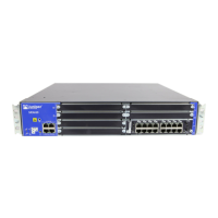
Table 7: SRX650 Services Gateway Front Panel Components (continued)
DescriptionLocationComponentNumber
The SRE/ACE 1.1 LED has the
following indicator colors:
•
Green and steadily on indicates
ACE 1.1 half slot is functioning
normally. Not applicable with SRE
full slot module.
•
Amber and steadily on indicates
ACE 1.1 half slot is initializing,
performing diagnostics, or going
down. Not applicable with SRE or
ACE full slot modules.
•
Red and steadily on indicates ACE
1.1 half slot failure. Not applicable
with SRE or ACE full slot modules.
•
Off indicates ACE 1.1 half slot is
empty.
NOTE: ACE modules will be
supported in a future release.
Left side of the
front chassis panel
SRE/ACE LED 1.111
Use the Power button to gracefully
shut down the services gateway and
the SRE. The SRE shuts down other
GPIMs first, then shuts itself down.
On a services gateway that has been
previously shut down using the
Power button, when depressed the
SRE will come back online. After the
SRE comes back online, it will bring
the other GPIMs online.
WARNING: The Power button does
not shut off power to the power
supplies or the midplane. You must
remove the power cables (DC PSU)
and power cords (AC PSU) to
completely shut down the services
gateway. The DC OK LED light on the
PSU changes from green to amber
indicating that the software has
stoppedrunning. During this time, you
can safely remove the SRE and any
GPIMs from the services gateway.
Left side of the
front chassis panel
Power button12
23Copyright © 2018, Juniper Networks, Inc.
Chapter 3: Chassis Description

 Loading...


