140 Keysight N9038A MXE Service Guide
Input Selection & Level Control
Input Selection & Level Control Section Troubleshooting
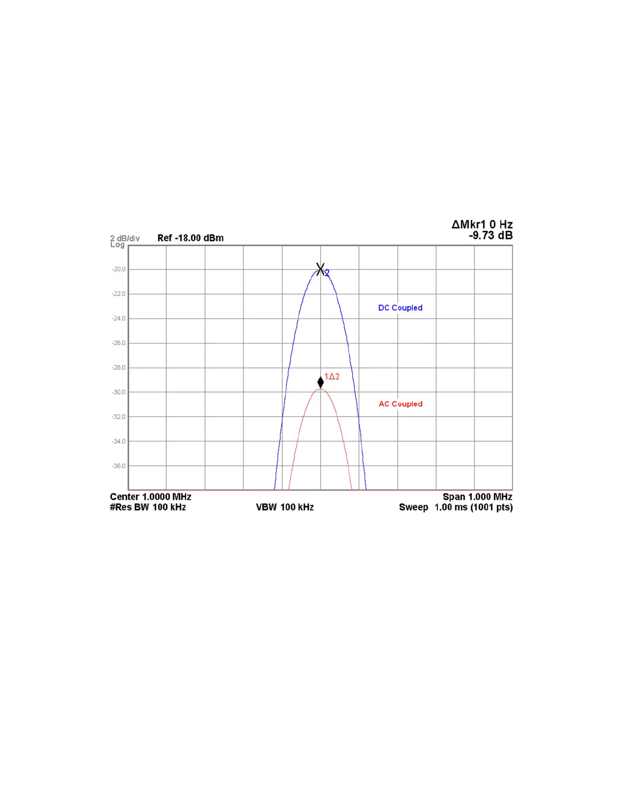
12.Verify that the signal level on the spectrum analyzer is at −20 dBm
(±0.25 dB), as shown in Figure 4-6, allowing for any additional test cable
loss.
If the signal level is incorrect the most likely cause of the problem is the A9
Attenuator A assembly itself. However, before replacing an A9 Attenuator
A assembly for any failure, refer to Chapter 8, “Front End Control.” for
information on how to verify the control signals to it.
Figure 4-6 A9 Attenuator A AC/DC Input Coupling
13.Turn on the Marker Delta function of the spectrum analyzer being used.
14.Change the instrument input coupling to AC by pressing Input / Output,
RF Input, RF Coupling AC.
15.Verify that the signal level on the spectrum analyzer drops by at least 5 dB
from where it was when the RF Coupling was set to DC, as shown in Figure
4-6.
If the signal level is incorrect the most likely cause of the problem is the A9
Attenuator A assembly itself. However, before replacing an A9 Attenuator
A assembly for any failure, refer to Chapter 8, “Front End Control.” for
information on how to verify the control signals to it.

 Loading...


