Keysight N9038A MXE Service Guide 141
Input Selection & Level Control
Input Selection & Level Control Section Troubleshooting
RF Input Selection
16.Move the signal generator to the A9 Attenuator A RF Input #1. Refer to
Figure 4-4 or Figure 4-5.
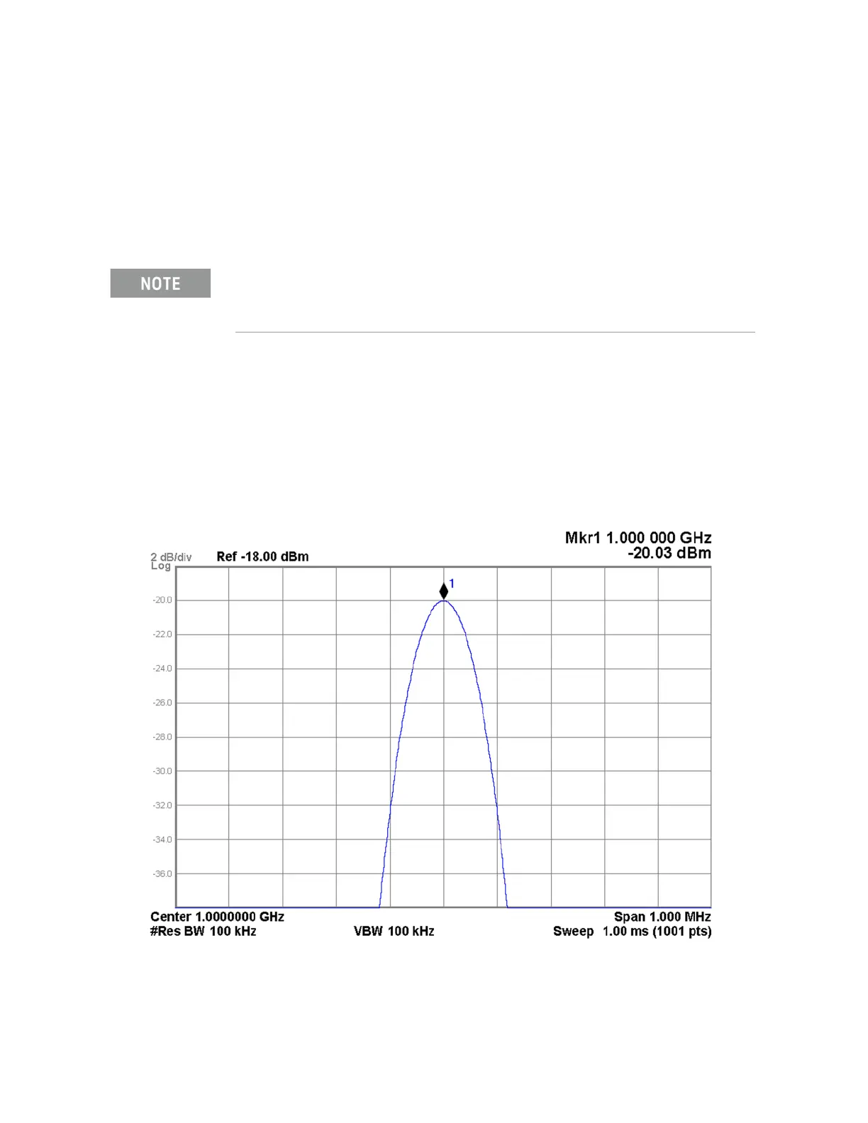
17.Tune the signal generator to 1 GHz with an amplitude of −20 dBm.
18.Tune the spectrum analyzer to 1 GHz with a span of 1 MHz.
19.Verify that the signal level on the spectrum analyzer is at −20 dBm
(±0.25 dB), as shown in Figure 4-7, allowing for any additional test cable
loss.
If the signal level is incorrect the most likely cause of the problem is the A9
Attenuator A assembly itself. However, before replacing an A9 Attenuator
A assembly for any failure, refer to Chapter 8, “Front End Control.” for
information on how to verify the control signals to it.
Figure 4-7 A9 Attenuator A RF Input #1
If there is a particular frequency of interest use that instead of the 1 GHz used in this example.

 Loading...


