158 Keysight N9038A MXE Service Guide
Input Selection & Level Control
Input Selection & Level Control Section Troubleshooting
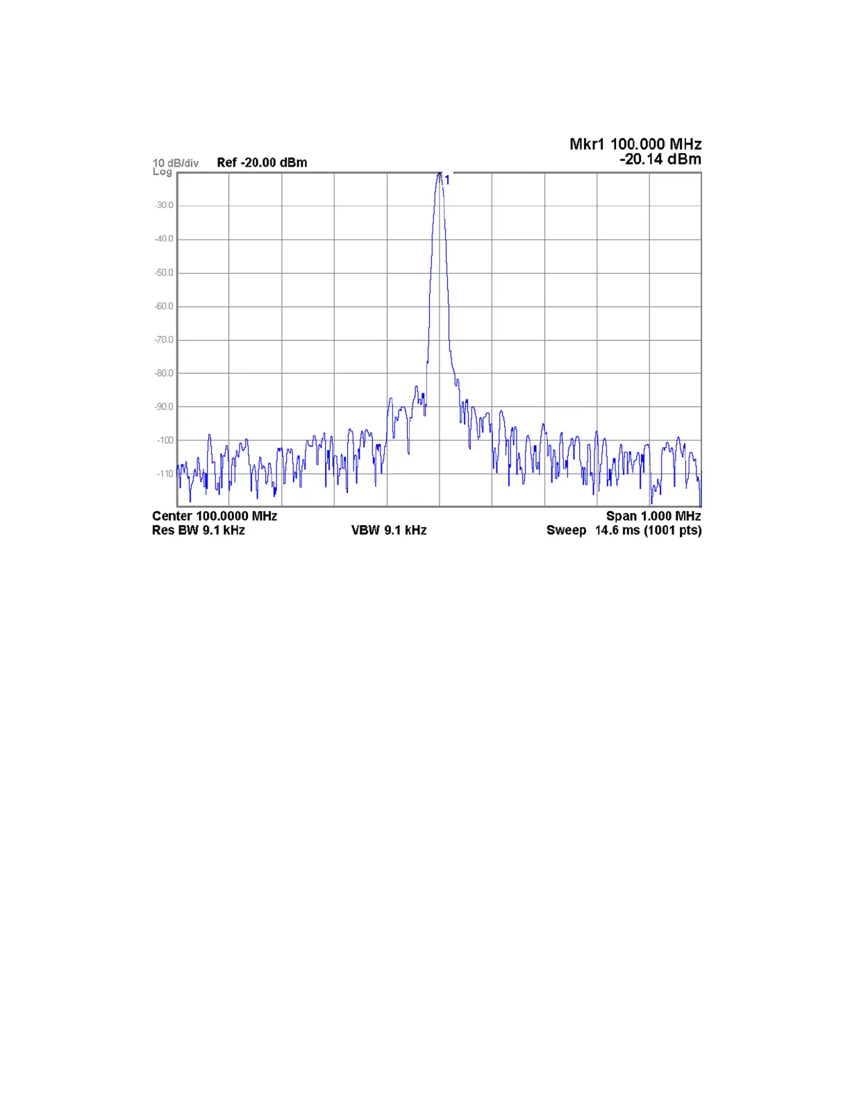
Figure 4-22 SW1 Cal Switch Signal Level
12.Move the signal generator to the SW1 Cal Switch Calibrator Input (P2), as
shown in Figure 4-21.
13.Switch the instrument to use the 50 MHz calibrator signal, which will
connect the SW1 Cal Switch Calibrator Input (P2) to the Output (PC), by
pressing Input / Output, RF Calibrator, 50 MHz.
14.Verify that the signal level on the spectrum analyzer is at −20 dBm
(±0.25 dB), as shown in Figure 4-22, allowing for any additional test cable
loss.
If the signal level is incorrect the most likely cause of the problem is the
SW1 Cal Switch itself. However, before replacing an SW1 Cal Switch for
any failure, refer to the “A21 RF Preselector Input Assembly” on page 175
for information on how to verify the control signals to it.
15.If no problem has been found with the functionality of the SW1 Cal Switch
carefully reconnect W27, W28, and W43 to the SW1 Cal Switch as shown
if Figure 4-20. Torque all cable connections to 10 in-lbs.

 Loading...


