Keysight N9038A MXE Service Guide 239
RF Downconverter Section
RF Downconverter Section Troubleshooting
14.If the low band signal path loss continues to be within the expected
values, proceed to the High Band Thru Path verification.
High Band Thru Signal Path
15.Referring to Figure 6-7 or Figure 6-8, remove W39 by disconnecting it
from the A11 RF Switch / High Band Preamp assembly high band output
(J3) and the A12 YTF input port.
16.Tune the signal generator to 6 GHz with an amplitude of -20 dBm.
17.Connect a spectrum analyzer to the A11 RF switch / High Band Preamp
assembly High Band Output (J3).
18.Tune the spectrum analyzer to 6 GHz with a span of 1 MHz.
19.Switch the A11 RF Switch / High Band Preamp assembly to the high band
signal path by pressing FREQ, 6 GHz.
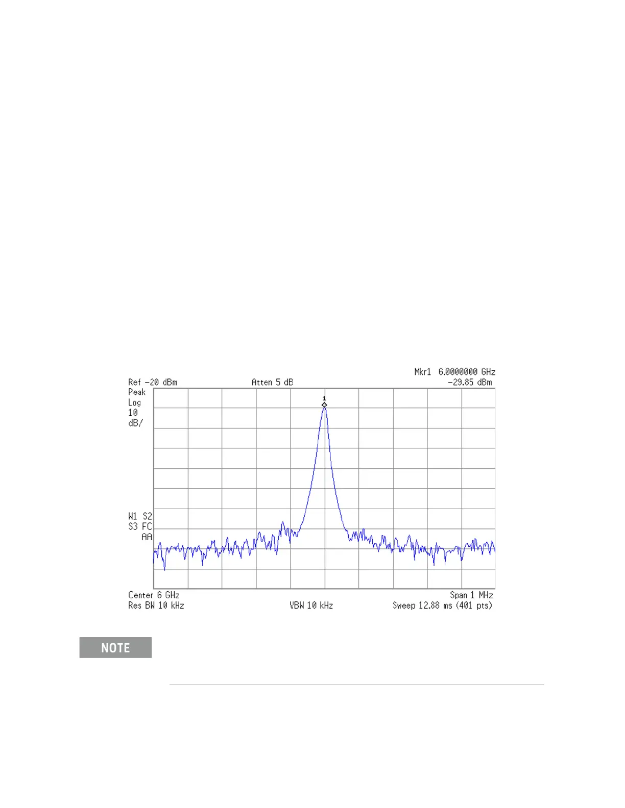
20.Verify that the signal amplitude on the spectrum analyzer display is
approximately what is expected, as outlined in Table 6-6 or Table 6-7,
allowing for any additional test cable loss, as seen in Figure 6-10.
Figure 6-10 A11 RF Switch / High Band Preamp - High Band Thru Signal Path
The isolation from the input port to the high band output port of the A11 RF Switch / High Band
Preamp when the input is switched to the low band path is less than 40 dB. Because of this, if
the signal path appears to be less than 40 dB too low it could be that the switch control lines
from the A15 Front End Control assembly are at fault.

 Loading...


