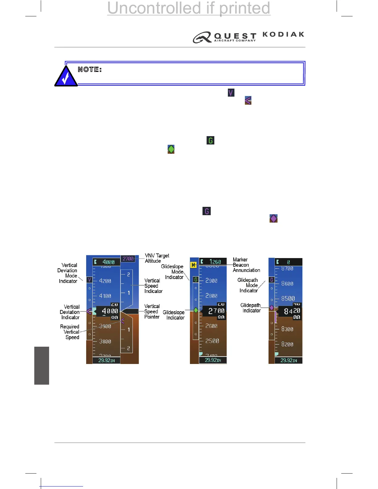
VERTICAL DEVIATION
The Vertical Deviation mode indicator appears as a above the Vertical
Deviation Indicator (VDI). The Vertical Deviation Indicator is a magenta
chevron indicating the baro-VNV vertical deviation when Vertical Navigation
(VNV) is being used. The VDI appears in conjunction with the “TOD within
1 minute” alert. The VDI is removed from the display if vertical deviation
becomes invalid.
The Glideslope mode indicator appears as a Vertical Deviation Indicator
(VDI). The Glideslope Indicator appears to the left of the Altimeter
whenever an ILS frequency is tuned in the active NAV eld. A green diamond
acts as the Glideslope Indicator, like a glideslope needle on a conventional
indicator. If a localizer frequency is tuned and there is no glideslope, “NO GS”
is displayed in place of the diamond.
The glidepath is analogous to the glideslope for GPS approaches supporting
WAAS vertical guidance (LNAV+V, L/VNAV, LPV). When an approach of this
type is loaded into the ight plan and GPS is the selected navigation source,
the Glidepath mode indicator appears as a Vertical Deviation Indicator
(VDI) and the Glidepath Indicator appears as a magenta diamond during
the approach. If the approach type downgrades past the nal approach x
(FAF), “NO GP” is displayed in place of the diamond.
Full-scale deection of two dots is 1000 feet.
NOTE: The Glidepath Indicator is only shown for aircraft with GIA 63W
Integrated Avionics Units, when WAAS is available.
Figure 7-22 – Vertical
Speed and Deviation
Indicator (VSI and VDI)
Figure 7-24 – Glidepath
Indicator
Figure 7-23 – Glideslope
Indicator
 Loading...