Home
Krone
Farm Equipment
Swadro 2000
Krone Swadro 2000 User Manual
4
of 1
of 1 rating
262 pages
Give review
Manual
Specs
To Next Page
To Next Page
To Previous Page
To Previous Page
Loading...
KRONE
operation
terminal
Gamma
43
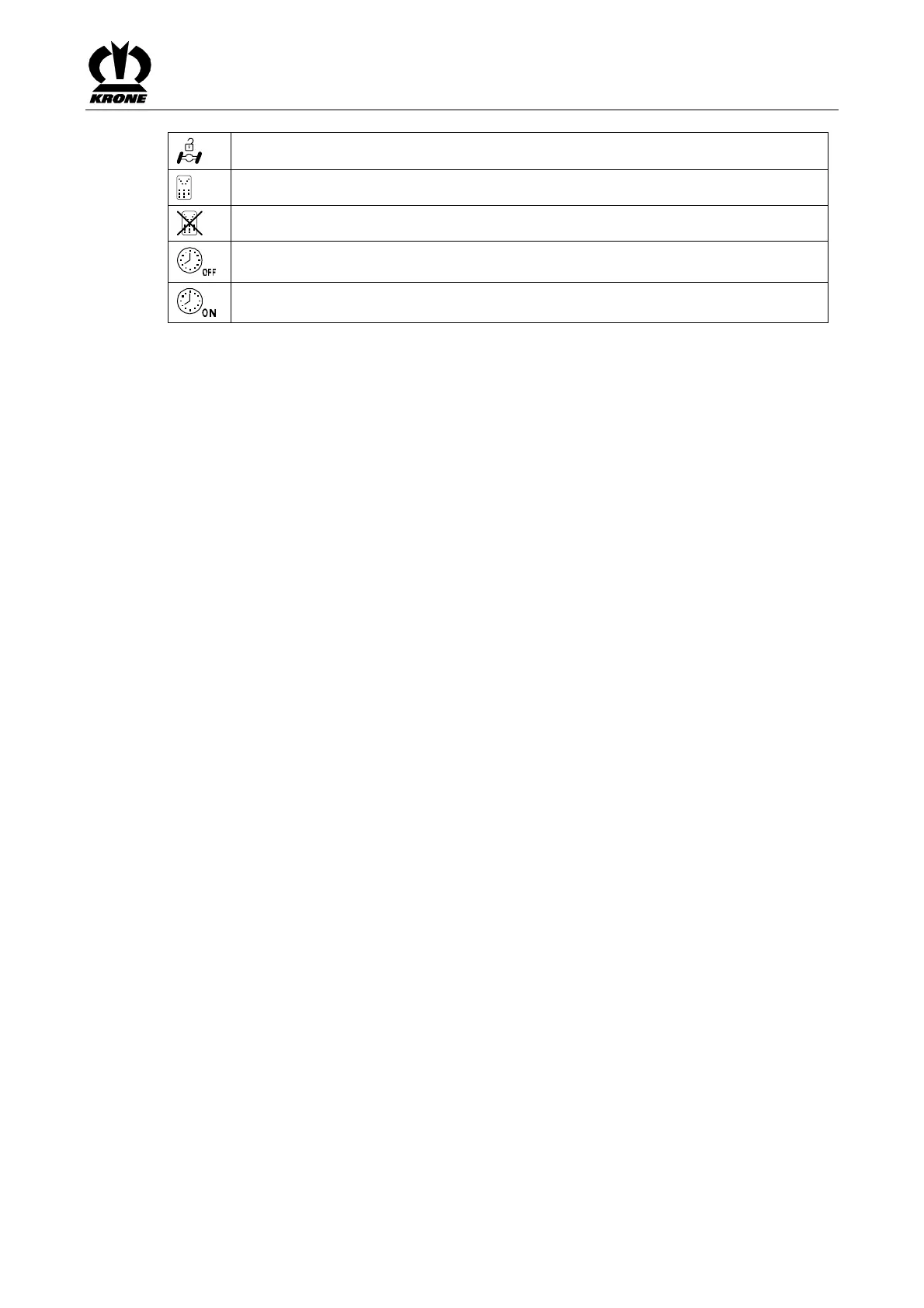
Self
steer
switched
on
(active)
Auxiliary
control
active
Auxiliary
control
inactive
Operating
hours
c
ounter
de
activated
Operating
hours
c
ounter
activate
d
Pos:
16.6.4
/BA/---
--Seitenumbruc
h------
@
0\
mod_1196175311
226_0.doc
@
4165
@
@
1
42
44
Table of Contents
Table of Contents
2
Table of Contents
3
Foreword
10
Introduction
11
General Description of the Machine
11
Validity
11
Identification Plate
11
Information Required for Questions and Orders
12
Intended Use
13
Road Traffic Regulations and Operating Permits
13
Machine Overview
14
Technical Data
15
Safety
16
Identifying Symbols in the Operating Instructions
16
Identification of the Hazard Warnings
16
Personnel Qualification and Training Fehler! Textmarke nicht Definiert
17
Dangers in Case of Non-Compliance with the Safety Instructions
17
Safety-Conscious Work Practices
17
Safety Instructions and Accident Prevention Regulations
18
Hitched Implements
19
PTO Operation
20
Hydraulic System
21
Tyres
21
Maintenance
21
Unauthorised Conversion/Modification and Spare Parts Production
22
Inadmissible Modes of Operation
22
Position of the Adhesive Safety Stickers on the Machine
23
Introduction
23
Safety Instructions on the Machine
23
Position of the General Information Labels on the Machine
26
Re-Ordering the Adhesive Safety and Information Labels
28
Affixing the Adhesive Safety and Information Labels
28
Contact
28
Commissioning
29
First Installation
29
Fitting the Protective Frames/Hoop Guards on the 6 Rotors
30
Requirements on the Tractor
32
Preparations on Tractor
32
Adjusting the Lower Suspension Arms
32
Table of Contents
33
Electrical Power Supply
33
Mounting Onto the Tractor
33
PTO Shaft
34
Length Adjustment
34
Height of Tractor Lower Suspension Arms
34
KRONE Operation Terminal Gamma
35
Mounting the Control Unit
36
Electrical Power Supply
37
Overview
38
Description of the Keys
39
Operational Readiness
41
Display Areas on the Screen
42
Status Line Area (I)
42
Displays in the Main Window (II)
44
Softkeys Area (III)
45
Softkeys Area (IV)
46
Road Travel" Basic Screen
48
Basic Screen "Lifting the Rotors
49
Lowering the Rotors from Transport to Headland Position
49
Lowering All Rotors to Headland Position
49
Lowering the Rotors from the Headland Position to the Working Position
50
Selecting the Rotors for a Function
50
Lowering Individual Rotors to Working Position
50
Lowering All Rotors to Working Position (Automatic Mode)
50
Adjusting the Automatic Time <Lower Rotors
51
Raising the Rotors to Headland Position
52
Raising Individual Rotors to Headland Position
52
Raising All Rotors to Headland Position (Automatic Mode)
52
Raising All Rotors from the Headland Position to the Transport Position
53
Basic Screen "Width Adjustments
54
Working Width
54
Adjust the Front Working Width
54
Swath Width
55
Adjusting the Swath Width
55
Raise/Lower Rotors in Pairs
56
Lowering Rotors to the Working Position in Pairs
56
Raising Rotors to the Headland Position in Pairs
56
Basic Screen "Working Height
57
Adjusting the Working Height of the Rotors
57
Rotor Height Automatic Mode
58
Menu Level
59
Short Overview
59
Bringing up a Menu Level
60
Main Menu 1 - Settings
62
Menu 1-2 "Zero Calibration Rotor Height" (Rotor Height Display Option)
63
Menu 1-3 "Overlap
64
Menu 1-4 „Unit of Measurement
65
Menu 1-5 "Contrast
66
Main Menu 2 - Counters
68
Menu 2-2 "Total Counters
71
Main Menu 3 „Manual Operation
72
Selecting the Rotors for a Function
74
Adjust the Front Working Width
75
Adjusting the Swath Width
76
Adjusting the Parallel Offset
77
Main Menu 4 - Service
79
Menu 4-2 "Manual Sensor Test
80
Actuator Test
85
Menu 4-4 "Manual Actuator Test
86
Main Menu 5 - Information
90
Main Menu 6 "Technician
91
Alarm Message
92
Alarm Messages
93
General Alarms
93
Logical Alarms
94
Physical Alarms
96
Control Unit - Auxiliary Control
99
Mounting
100
Electrical Power Supply
101
Overview of Auxiliary Control
102
Operational Readiness
104
Lowering the Rotors from Transport to Headland Position
105
Lowering All Rotors to Headland Position
105
Lowering the Rotors from the Headland Position to the Working Position
106
Lowering Individual Rotors to Working Position
106
Lowering the Rotors in Pairs
106
Lowering All Rotors to Working Position (Automatic Mode)
106
Table of Contents
108
Raising the Rotors from the Working Position to the Headland Position
108
Raising Individual Rotors to the Headland Position
108
Raising the Rotors in Pairs
108
Raising All Rotors to Headland Position (Automatic Mode)
108
Raising All Rotors from the Headland Position to the Transport Position
109
Adjusting the Working Width
110
Adjust the Front Working Width
110
Alarm Messages
110
Malfunctions - Causes and Remedies
110
KRONE ISOBUS-Terminal CCI 100
111
Installing the Terminal into Cabin
112
ISOBUS Short Cut Button
113
Connecting the Terminal (on Tractors with Integrated ISOBUS System)
115
Connecting the Terminal (on Tractors Without ISOBUS System)
116
Connecting the Multi-Function Lever to the CCI Terminal
117
Switching the Terminal on / off When the Machine Is Not Connected
118
Switching the Terminal on / off When the Machine Is Connected
119
Display Areas on the Screen
120
Status Line Area (I)
121
Displays in the Main Window (II)
122
Basic Screen "Width Adjustments
125
Working Width
125
Swath Width
126
Basic Screen "Working Height
127
Adjusting the Working Height of the Rotors
127
Basic Screen „Lifting the Rotors
128
Lowering the Rotors from Transport to Headland Position
128
Lowering All Rotors to Headland Position
128
Lowering the Rotors from the Headland Position to the Working Position
129
Lowering Individual Rotors to the Working Position
129
Lowering Rotors to the Working Position in Pairs
129
Lowering All Rotors to Working Position (Automatic Mode)
129
Adjusting the Automatic Time <Lower Rotors
130
Raising the Rotors to Headland Position
131
Raising Individual Rotors to the Headland Position
131
Raising Rotors to the Headland Position in Pairs
131
Raising All Rotors to the Headland Position (Automatic Mode)
132
Adjusting the Automatic Time <Raise Rotors
132
Raising All Rotors from the Headland Position to the Transport Position
133
Menu Level
135
Brief Overview
135
Calling up the Menu Level
136
Main Menu 1 "Settings
137
Menu 1-2 "Zero Calibration Rotor Height" (Rotor Height Display Option)
138
Menu 1-3 "Overlap
139
Main Menu 2 "Counters
140
Menu 2-1 "Customer Counter
141
Menu 2-2 "Total Counters
144
Main Menu 3 „Manual Operation
145
Manual Mode "Working Width / Swath Width / Parallel Offset
147
Adjusting the Parallel Offset
148
Manual Mode "Guide Wheels / Self Steer
149
Fold Guide Wheels Up/Down
149
Manual Mode "Lifting the Rotors
150
Selecting the Rotors for a Function
150
Main Menu 4 "Service
151
Menu 4-2 "Manual Sensor Test
152
Actuator Test
157
Menu 4-4 „Manual Actuator Test
158
Main Menu 5 "Information
162
Main Menu 6 „Fitter
163
Main Menu 9 "ISO Settings Info
164
Menu 9-1 "Softkeys ISO Terminal
165
Menu 9-2 "Switching between Terminals
166
Alarm Message
167
Alarm Messages
168
General Alarms
168
Logical Alarms
169
Physical Alarms
170
ISOBUS Operation
173
Attaching the ISOBUS Terminal
174
Connection Terminal to Tractor
174
Connection Tractor to Machine
174
Differing Functions to KRONE ISOBUS Terminal CCI
175
Menu 4-7 "Diagnostics Auxiliary (AUX)
176
Main Menu 9 "ISO Settings Info
177
Menu 9-1 "Softkeys ISO Terminal
178
Menu 9-2 "Switching between Terminals
179
ISOBUS „Auxiliary"-Function (AUX)
180
Example of a Joystick Assignment for Fendt (Default Setting)
182
Start-Up
183
Mounting Onto the Tractor
183
Table of Contents
184
Hydraulics
184
Special Safety Instructions
184
Connecting the Hydraulic Lines
185
Lighting Connection
186
Connecting the Electrical Controls
187
Compressed Air Connections for the Compressed Air Brake
188
Moving the Machine Without Tractor
189
Hydraulic Brake (Export)
189
Install the PTO Shaft
190
Parking Brake
191
Driving and Transport
192
Operation
193
Overload Protection
193
From Transport into Working Position
194
Removing the Tine Guards from the Tine Tips
194
Lowering the Rotor Arms into Working Position
194
Adjusting the Raking Height
195
Auxiliary Steering
196
Move Auxiliary Steering to Centre Position
196
Travelling on an Incline
197
Travelling Speed und Drive Speed
197
Switching from Working Position to Transport Position
198
Raising the Rotor Arms to Transport Position
198
Protecting the Tine Tips (Transport Position and Swather Switched Off)
199
Parking
200
Settings
202
To Adjust the Rotor Running Gear
202
Setting the Lifting Height in Headland Position
203
Adjustable Throttles
204
Maintenance
205
Special Safety Instructions
205
Spare Parts
205
Tightening Torques
206
Tightening Torques (Countersunk Screws)
207
Testing the Screws on the Tines
207
Tyres
208
Checking and Maintaining Tyres
208
Replacing the Tine Arms(in Case of Repair)
210
Position of the Sensors
212
Adjusting the Sensors
214
Namur Sensor D = 12 MM
214
Namur Sensor D = 30 MM
214
Maintenance - Hydraulic System
215
Load-Sensing Connection
216
Adjusting the Hydraulic System
217
Emergency Manual Activation
217
Preparing the Machine for Road Travel (in Emergency Manual Mode)
219
Parallel Offset
221
Moving All Rotor Arms from Working Position to Transport Position
221
Retracting the Hydraulic Cylinder for the Working Width and for the Swath Width
223
Raising the Right and Left Supporting Wheels
223
Moving the Auxiliary Steering to the Centre Position
223
Activating the Self Steer
223
Hydraulic System Circuit Diagrams
224
High-Pressure Filter
226
Maintenance - Lubrication Chart
227
Special Safety Instructions
227
PTO Shaft
227
Maintenance - Lubrication Chart
228
Lubrication Chart
228
Maintenance - Gearbox
230
Filling Quantities and Lubrication Designations for Gearboxes
230
Rotor Gear
231
Angular Gearbox
231
Maintenance - Brake System
232
Air Filter for Pipe
233
Compressed-Air Reservoir
234
Special Equipment
235
Tine Loss Safeguard
235
Placing in Storage
236
Special Safety Instructions
236
At the End of the Harvest Season
237
Before the Start of the New Season
238
Special Safety Instructions
238
Malfunctions - Causes and Remedies
239
Special Safety Instructions
239
Electrical Circuit Diagram
241
4
Based on 1 rating
Ask a question
Give review
Questions and Answers:
Need help?
Do you have a question about the Krone Swadro 2000 and is the answer not in the manual?
Ask a question
Krone Swadro 2000 Specifications
General
Brand
Krone
Model
Swadro 2000
Category
Farm Equipment
Language
English
Related product manuals
Krone Swadro 800/26
64 pages
Krone Swadro 35
38 pages
Krone Swadro 46
38 pages
Krone Swadro 900
64 pages
Krone Swadro 700
64 pages
Krone Swadro 355
26 pages
Krone Swadro 395
26 pages
Krone Swadro 42 T
66 pages
Krone Swadro 46 T
66 pages
Krone Swadro TC 760
138 pages
Krone Swadro TS 620
148 pages
Krone Swadro TC 680
138 pages