Maintenance
214
Pos: 40.29 /Überschrif ten/Überschrif ten 3/A-E/Ein stellung der S ensoren @ 0\mo d_119996217 3428_78.doc @ 37635 @ 3 @ 1
14.8.1 Adjusting the Sensors
Pos: 40.30 /BA/ Wartung/Sensor en/Namursensor d= 12 mm @ 0 \mod_1199962 247038_78.doc @ 37654 @ 4 @ 1
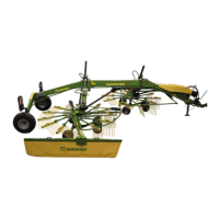
14.8.1.1 Namur sensor d = 12 mm
a
BP-VFS-088-1
2
1
3
Figure 154
The dimension between the encoder (2) and the sensor (1) must be "a" = 2 mm .
Setting
• Loosen the nuts on either side of the sensor.
• Turn the nuts until dimension "a" = 2 mm is reached.
• Tighten the nuts again.
Pos: 40.31 /BA/ Wartung/Sensor en/Namursensor d= 30 mm @ 0 \mod_1199962 520100_78.doc @ 37673 @ 4 @ 1
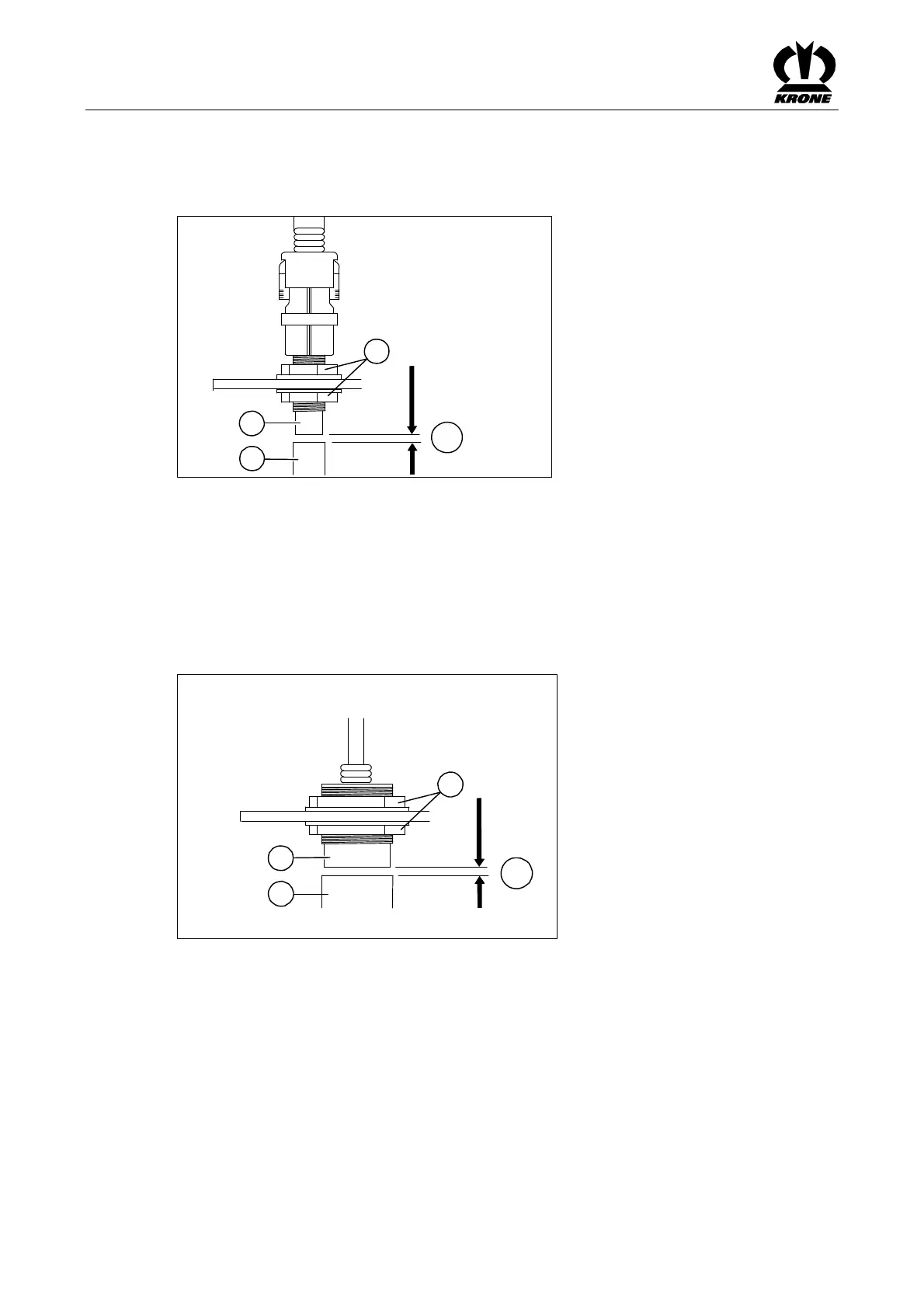
14.8.1.2 Namur sensor d = 30 mm
a
BPXC0172
2
1
3
Figure 155
The dimension between the encoder (2) and the sensor (1) must be "a" = 5 mm .
Setting
• Loosen the nuts on either side of the sensor.
• Turn the nuts until dimension "a" = 5 mm is reached.
• Tighten the nuts again.
Pos: 40.32 /BA/--- --Seitenumbruc h------ @ 0\mo d_119617531 1226_0.doc @ 41 65 @ @ 1