7-10 824 Reference Manual 11/8/00
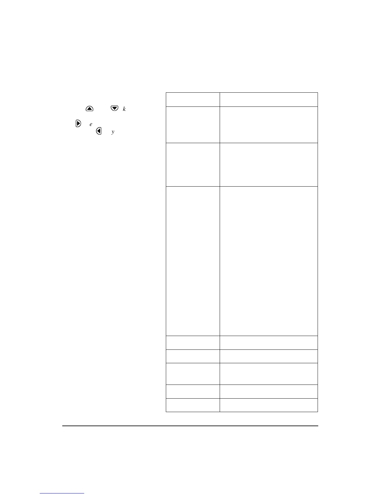
The following is the menu layout for the control settings:
Menu Items Available Settings Options
AC/DC Output AC-1 AC-2
AC-1 DC
AC-2 DC
AC-2 AC-1
Logic-In Mode None
Pause
Toggle
Level
Alarm
Logic-Out Off
RMS
Peak
R+P
Intv
R+I
P+I
R+P+I
A:D
R+A
P+A
R+P+A
I+A
R+I+A
P+I+A
R+P+I+A
R/S
Excd
Logic-Out Time 0 - 255 sec
Logic-Out #2 Same settings as Logic-Out
Logic-Out #2
Timer
0 - 255 sec
Heater On Yes/No
E.A. Cal Tone Yes/No
NOTE: The Logic-out #2, uses the
Heater output line if set to something
other than off.
Use the
u
and
d
keys to move
from one setting to the next. Then use
the
r
key to change the selected
setting. The
l
key is used to return
to previous menus.
Triggering for the SSA instrument is
for Logic out only. If Logic-Out is set
to “RMS”, the 824 looks at the level
set under “SPL Excd Lvl 1”. See
page 7-21.