B-2 824 Reference Manual 9/12/00
Interface Cables
Serial Port communications are made through the 8-pin con-
nector at the base of the Model 824. The instrument’s signals
conform to the RS-422 standard and are compatible with
RS-232C. The connectors use the same pin out and cables as
Apple® Macintosh® computers.
Connection to a computer
using CBL006
Step 1
With the instrument turned off, insert the cable
connector in the instrument’s 8-pin port.
Step 2
Connect the CBL006 cable to the serial port of the
computer, using the supplied 9 to 25 pin adapter as
necessary.
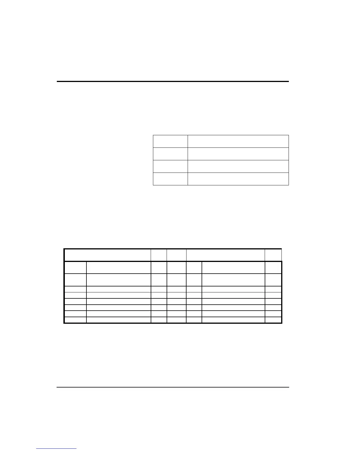
Pin configurations for the CBL006 follow:
CBL006 824 to computer cable (9 pin female ‘D’)
CBL002 824 to serial printer (25-pin male ‘D’)
CBL003 824 to modem cable (25 pin male ‘D’)
CBL091 824 to HP LaserJet (9 pin male ‘D’)
824 8-pin Connector End
Type Computer 9-pin RS-232C
Connector End
Ty pe
HSO Pin 1 Handshake Out O RS-232 DSR
CTS
Pin 6 DataSet Ready
Pin 8 Clear to Send
I
I
HSI Pin 2 Handshake In O RS-232 CD
DTR
Pin 1 Carrier Detect
Pin 4 Data Terminal Ready
I
O
TXD- Pin 3 Transmitted Data (-) O RS-422 RD Pin 2 Receive Data I
GND Pin 4 Ground X RS-422 GND Pin 5 Ground X
RXD- Pin 5 Received Data (-) I RS-422 SD Pin 3 Send Data O
TXD+ Pin 6 Transmitted Data (+) O RS-422 No connection
CXI Pin 7 Com. Extra Input I RS-232 No connection
RXD+ Pin 8 Received Data (+) I RS-422 GND Pin 5 Ground X