10-14 824 Reference Manual 11/8/00
Logic Out
The Logic Out bit value determines which lines (heater, cal,
or logic) will be used on the control connector to indicate
each of the five states.
• 0 - 65535
These lines can be used to control
lights in a remote control device to
indicate the current state.
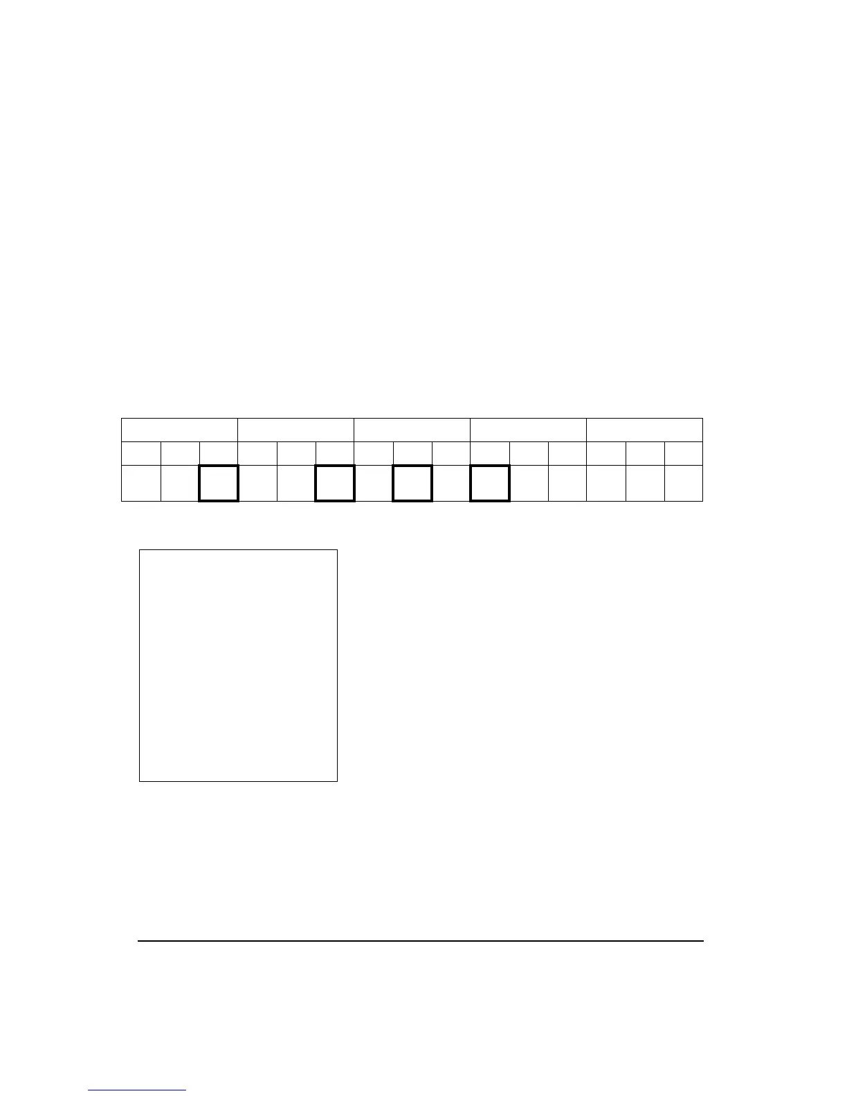
The setting for the Output Logic state selection is combined
into one 15-bit setting that has 3 bits (one for each output-
line-Logic Out, Heater Out, and Cal Out) for each of the five
states (Stop, Ready, Armed, Triggered, Ended).
Use the table below to determine how these will be set up.
The default setting is 04768 which is shown by the bolded
squares in the table above.
The Logic output is on pin 2 of the control connector and
will be driven to +5 volts through a 1000 ohm resistor when
asserted or zero volts when not asserted. Pin 1 is the ground
signal.
The Cal output is on pin 7 of the control connector and will
be driven to +5 volts through a 10,000 ohm resistor when
asserted and to zero volts when not asserted.
The Heater control output is on pin 8 of the control connec-
tor and will conduct current to ground when asserted and not
conduct when not asserted; uses an open drain ‘N’ channel
transistor. Maximum voltage is +40 VDC and -0.5 VDC and
the maximum current is 100 mA. Return current path is
through pin 1, control ground.
Ended Triggered Armed Ready Stop
16384 8192
4096 2048 1024 512 256 128
64 32 16 8 4 2 1
Heat Cal
Logic
Out
Heat Cal
Logic
Out
Heat Cal
Logic
Out
Heat Cal
Logic
Out
Heat
Cal
Logic
Out
The default setting indicates the
following:
Ended state is output on logic out.
Triggered state is output on logic
out.
Armed state is output on cal.
Ready state is output on heat.
Stop state is not outputed.
For more information on the con-
trol connector, see chapter 1.