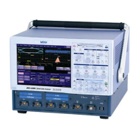
In low-pass filtering: The spectrum of a
square signal before (left top) and after (left
bottom) enhanced resolution processing. The
result clearly illustrates how the filter rejects
high-frequency components from the signal.
The higher the bit enhancement, the lower the
resulting bandwidth.
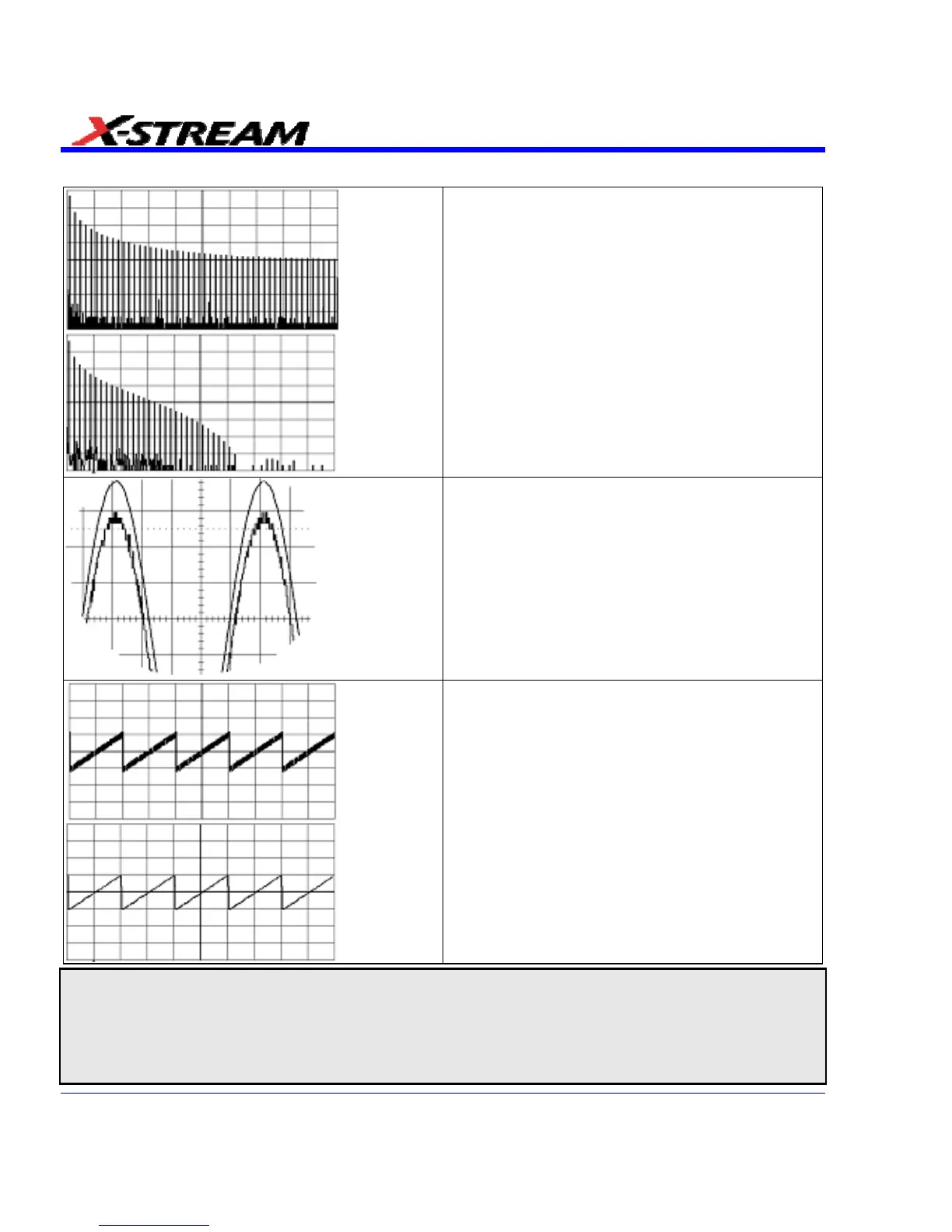
To increase vertical resolution: In the
example at left, the lower ("inner") trace has
been significantly enhanced by a three-bit
enhanced resolution function.
To reduce noise: The example at left shows
enhanced resolution of a noisy signal. The
original trace (left top) has been processed by a
2-bit enhanced resolution filter. The result (left
bottom) shows a "smooth" trace, where most of
the noise has been eliminated.
Note: Enhanced resolution can only improve the resolution of a trace; it cannot improve the accuracy or linearity of the
original quantization. The pass-band will cause signal attenuation for signals near the cut-off frequency. The highest
frequencies passed may be slightly attenuated. Perform the filtering on finite record lengths. Data will be lost at the start
and end of the waveform: the trace will be slightly shorter after filtering. The number of samples lost is exactly equal to the
length of the impulse response of the filter used: between 2 and 117 samples. Normally this loss (just 0.2 % of a 50,000
point trace) is not noticed. However, you might filter a record so short there would be no data output. In that case,
however, the instrument would not allow you to use the ERES feature.
186 SDA-OM-E Rev H