SDA Operator’s Manual
5. Touch the Show Error Map checkbox to enable a display of the error map. The error map
displays bit errors in a three-dimensional display, with errors shown in white and correct bits
in dark gray. The display is a 2-color surface map with frame number in the Y direction and
bit number in the X direction. A frame is indicated by the frame sync bit sequence and is
composed of the bits from the end of one frame sync to the start of the next one. If frame
sync bits are not specified, the bits are laid out in fixed-length rows, starting at the top left
corner of the screen and proceeding from left to right and top to bottom in a raster pattern.
6. Touch the Show Params checkbox to display parameters BER, Nbits, False0, and False1.
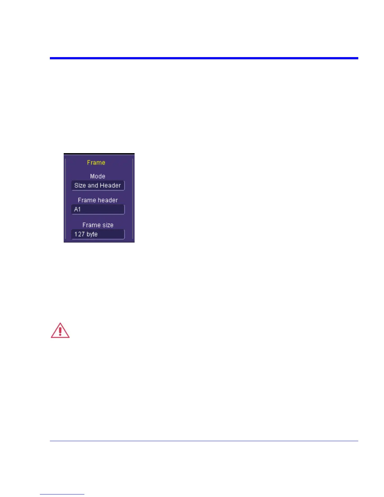
7. You can use the fields under Frame, to align the same bits one on top of the other so that bit
failures will appear as vertical lines.
Touch inside the Mode field and make a selection from the pop-up menu.
8. If you selected Header or Size and Header, touch inside the Frame header field and enter a
hexadecimal number representing the prefix before the actual data. This prefix will be ignored
and only the data will be examined. If you selected Size or Size and Header, touch inside the
Frame size field and enter the number of bytes in the frame, using the pop-up keypad.
Frame size divides your waveform into equal pieces of the size that you enter.
Serial Trigger
Warning
To prevent damage to the serial trigger module, never apply external voltages to the clock
and data output connectors.
The SDA "A" models include a serial pattern trigger, and a Clock and Data Recovery module.
This CDR module is built into the instrument and is accessible through the channel 4 input. The
signal on channel 4 is always present at the input to the serial pattern trigger module. The serial
trigger also includes two outputs that are located on the front panel just to the left of the channel 4
input. These two SMA jacks allow access to the recovered clock and data signals from the serial
trigger module. The signals at these connectors are nominally zero mean with a peak-to-peak
amplitude of 330 mV.
SDA-OM-E Rev H 321