SDA Basic Setup
Note: Many of the measurements in the SDA require both a high sampling rate and long memory to compute accurately.
Verify that you are in two channel mode (20 GS/s) and that at least 400k samples are being captured before performing
any SDA measurements. Lower sampling rates can result in less accurate jitter measurements, and short record lengths
can give incomplete eye patterns or jitter displays that diverge.
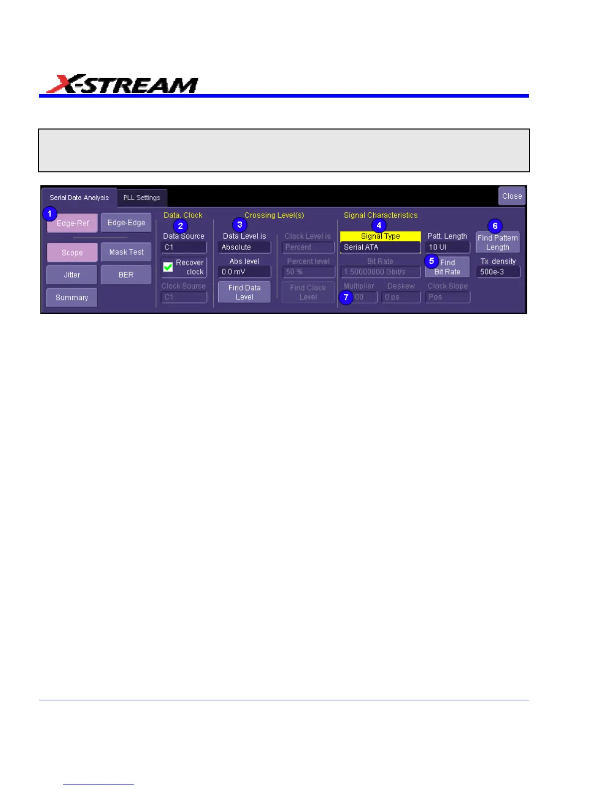
1. To access the SDA dialogs, press the Serial Data front panel button; or, touch Analysis in
the menu bar, then Serial Data in the drop-down menu. The display defaults to the Scope
dialog, which enables you to set up SDA measurements while you continue to view currently
displayed waveforms. Touching the Scope button turns off SDA features. In the image
above are shown two measurement modes: Edge-Ref and Edge-Edge. The Edge-Edge
mode is optional and only available with the ASDA-J option. If this option is not present, the
two mode buttons are not displayed. The Edge-Edge mode is explained separately in this
manual; the information presented here applies mainly to the standard (Edge-Reference)
mode.
2. Touch inside the Data Source field and select a data source, then touch inside the Clock
Source field and select a clock input. If you want to recover the clock from the signal, touch
the Recover clock checkbox; the Clock Source field will become inactive. The "Crossing
level(s)" section in this dialog allows you to set the voltage level at which the signal timing is
measured. The crossing level is set separately for the data and clock (if an external clock is
selected) and can be either absolute or relative. The Absolute crossing level in volts (or
watts for an optical signal) can be set directly, or can be found automatically by touching the
Find Data Level button. The level is found by locating the midpoint between the highest and
lowest signal levels in the current acquisition. The Relative level is automatically set to the
selected percentage on each acquisition.
312 SDA-OM-E Rev H