6. The Pattern Length control sets the repetition length of the data pattern in the signal under
test. Serial data signals generally transmit a repeating data pattern of some sort. For example
a PRBS7 pattern repeats every 127 bits while a K28.5 repeats every 20 bits. Enter the
pattern length in the Pattern Length control. Alternatively, the SDA can automatically find the
pattern length by means of the Find Pattern Length button. The Find Pattern Length
control determines the pattern repetition length (if any) in the current acquisition and sets the
Pattern length control to this value. The Pj measurement uses the pattern length value to
determine which peaks in the jitter spectrum are caused by the pattern repetition. An
incorrect value in the Pattern Length control will result in overestimation of the Pj and, as a
result, underestimation of the random jitter.
7. The Tx Density control indicates the ratio of transitions in the data record to the total number
of bits in the signal. Normally, an NRZ data stream does not have transitions during every bit
interval. For example, there are cases where adjacent 1 or 0 values exist. On average,
approximately 50% of the bit intervals have transitions, so the Tx density is 500e-3. The
actual acquired data set may have a transition density different from 50%, however. The total
jitter measurement uses this transition density to normalize the measured histogram into a
pdf [probability density function]. Many instruments simply assume 50% when performing this
normalization, which can lead to errors. These errors are eliminated in the SDA through the
use of the measured transition density in the normalization process. The Tx density is
automatically measured when the Find Pattern Length button is pressed.
Edge-Edge Jitter Measurements
Jitter measurements are enabled by selecting Jitter in the SDA main menu when the mode is set
to Edge-Edge. The available displays include a jitter bathtub curve, TIE histogram, ISI display,
and N-cycle vs. N plot.
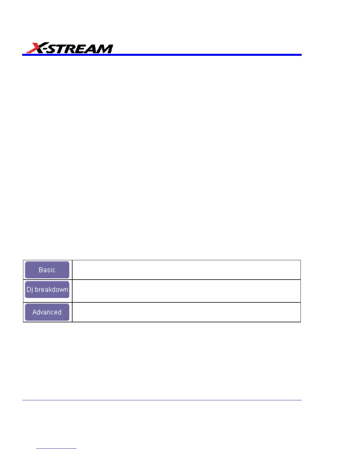
The Measurement buttons control which jitter measurements are displayed.
The Basic button displays the total jitter (Tj), Random jitter (Rj), and the
deterministic jitter (Dj).
The Dj Breakdown button enables the display of the components of Dj ---
periodic jitter (Pj), duty cycle distortion (DCD), and data dependent jitter (DDj) --
- in addition to the basic Rj, Dj, and Tj.
The ASDA-J option adds the Advanced button which, when selected, replaces
the Tj, Rj, Dj display with the peak-to-peak and rms values of the filtered jitter.
342 SDA-OM-E Rev H