Gated (Qualified) Eye Diagram
The Gated Eye Diagram mode utilizes a separate signal (the “Gate” or qualifier) to create dual
eye diagrams based on the polarity of the Gate.
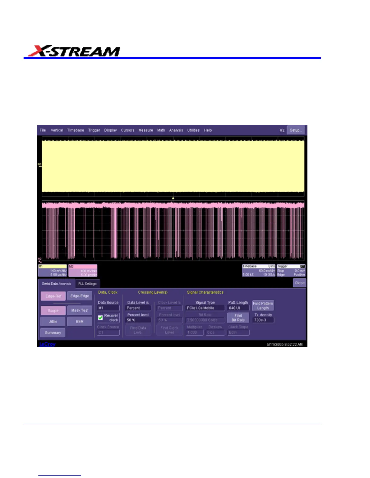
Here’s an example of a gated eye diagram. Channel 1 (M1) contains the raw data and Channel 2
(M2) contains a Gate signal. While the Gate signal is high, the UIs will transfer to Eye display;
When the Gate signal goes low, the UIs will transfer to Eye2 display
Data (M1) and Gate (M2) signal sources
364 SDA-OM-E Rev H