Determining Trigger Level, Slope, Source, and Coupling
Level defines the source voltage at which the trigger circuit will generate an event: a change in
the input signal that satisfies the trigger conditions. The selected trigger level is associated with
the chosen trigger source.
Trigger level is specified in volts and normally remains unchanged when you change the vertical
gain or offset. The amplitude and range of the trigger level are limited as follows:
• ±4.1 screen divisions with a channel as the trigger source
• ±400 mV with EXT as the trigger source
• ±4 V with EXT/10 as the trigger source
• ±40 mV with EXT*10 as the trigger source
• None with LINE as the trigger source (zero crossing is used).
Coupling refers to the type of signal coupling at the input of the trigger circuit. Because of the
instrument's very high bandwidth, there is only one choice of trigger coupling: DC 50 . However,
as a visual check of where ground is, you may switch the channel to ground coupling at any time
while testing.
With DC coupling, all of the signal's frequency components are coupled to the trigger circuit for
high-frequency bursts.
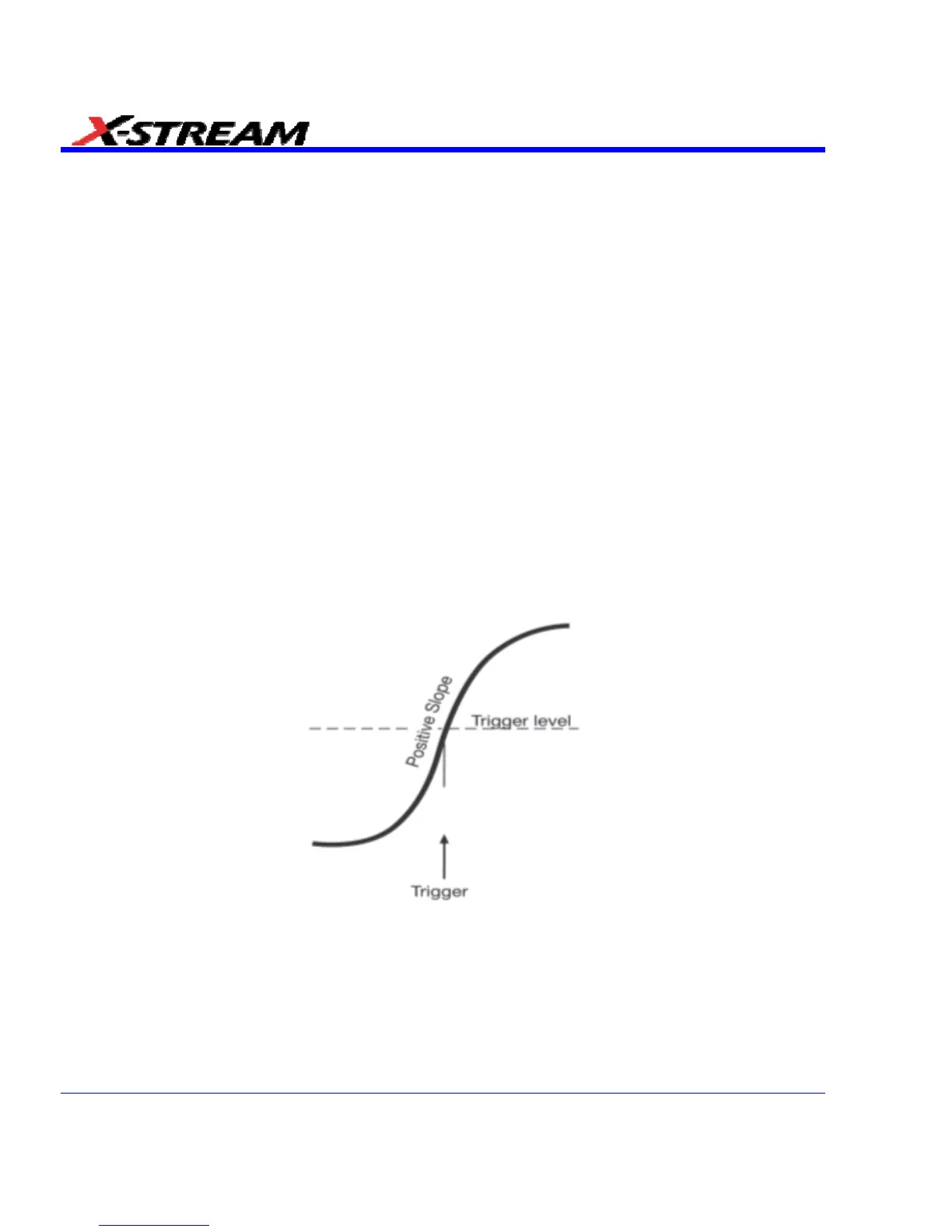
Slope determines the direction of the trigger voltage transition used for generating a particular
trigger event. You can choose a positive or negative slope. Like coupling, the selected slope is
associated with the chosen trigger source.
Edge trigger works on the selected edge at the chosen level. The slope (positive or negative) is specified in the
Trigger label permanently displayed below-right of the grid.
76 SDA-OM-E Rev H