SDA Operator’s Manual
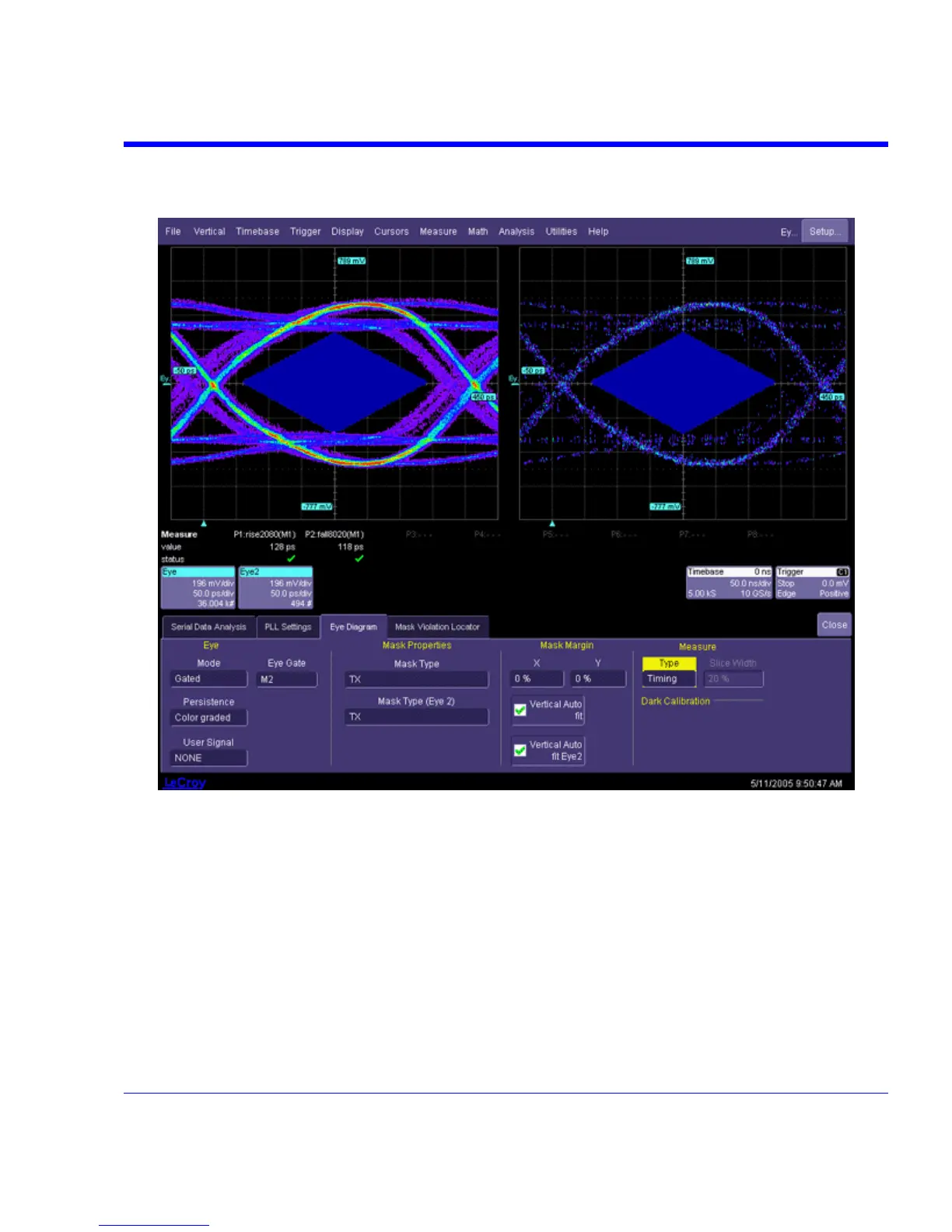
The following is the Eye diagram resulting from applying the Gate signal. When the Gate is high,
the bit data goes to one eye diagram. When the Gate is low, data goes to the other eye.
Gated Eye Diagram Example
SDA THEORY
The SDA operates by processing a long signal acquisition. The processes include clock recovery,
eye pattern computation, jitter measurement, and bit error testing. All of these operations are
performed on the same data record. The processes are described in detail in this section.
Clock recovery
An accurate reference clock is central to all of the measurements performed by the SDA. The
recovered clock is defined by the locations of its crossing points in time. Starting with zero, the
clock edges are computed at specific time intervals relative to each other. A 2.5 GHz clock, for
example, will have edges separated in time by 400 ps.
SDA-OM-E Rev H 365