Operating elements for crane operation
9.2 Short description of the operating elements
Operating manual 3 302 736 en 9 - 137
GMK4090
xx.xx.xxxx
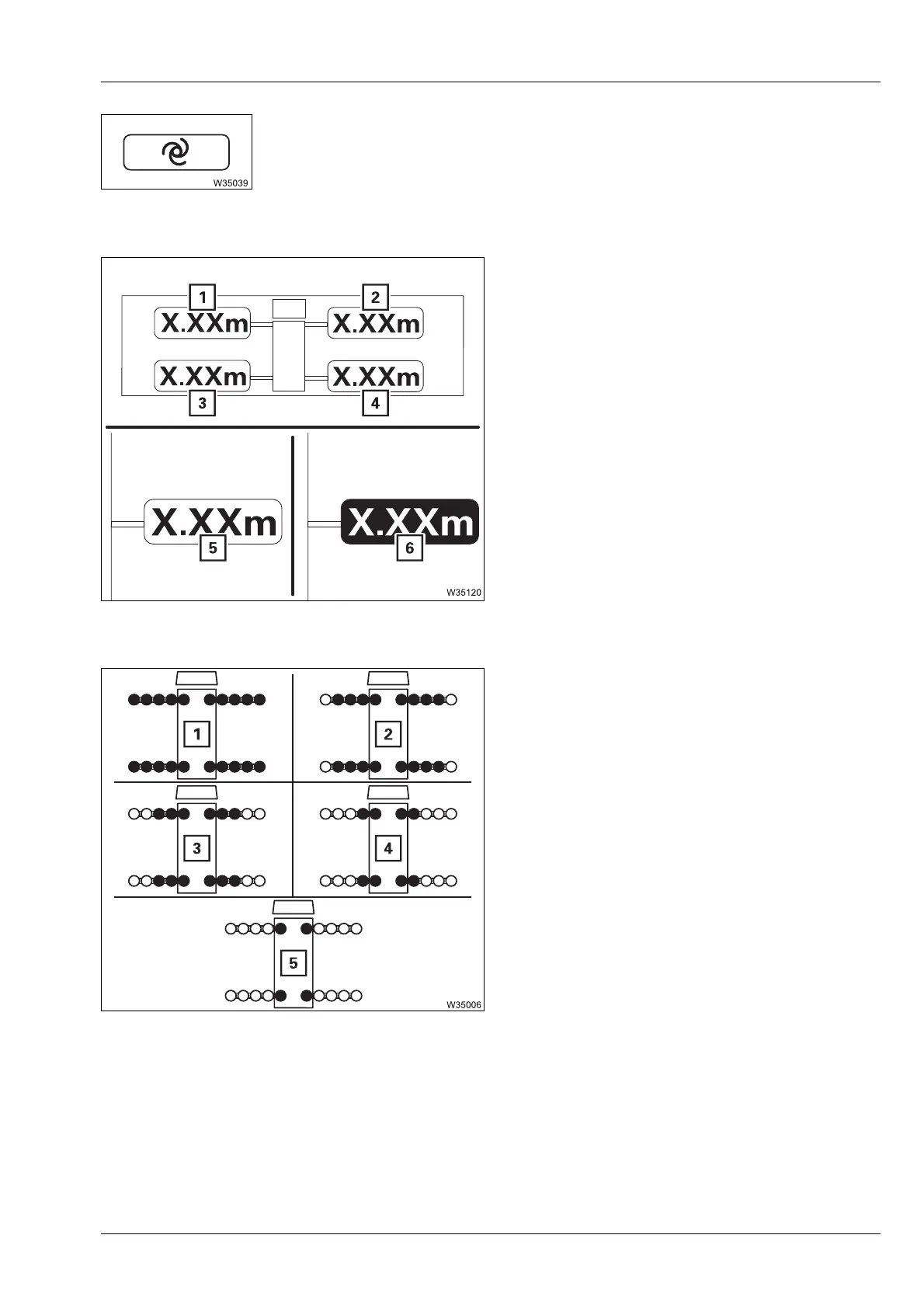
Accept the measured outrigger span
Select and confirm – the outrigger span provided by the outrigger width
monitoring is adopted and shown on the
Enter outrigger span display;
à Confirm the rigging mode and lifting capacity table, p. 11 - 39.
Enter outrigger span
(
MAXbase)
The values are entered individually for
outrigger beams (1) to (4).
In input mode – select and confirm the
individual widths.
Outrigger span monitoring display
(
MAXbase)
à Enter rigging mode, p. 11 - 30
Enter outrigger span
(
Standard)
The selection occurs simultaneously for all
outrigger beams – selected outrigger widths
are orange.
In input mode – select and confirm the
outrigger span
à Enter rigging mode, p. 11 - 30
s
5 Measured outrigger width = required
width
6 Measured outrigger width of required
width
1 8.660 x 7.200 m (28.4 x 23.6 ft)
2 8.660 x 6.250 m (28.4 x 20.5 ft)
3 8.660 x 5.300 m (28.4 x 17.4 ft)
4 8.660 x 3.800 m (28.4 x 12.4 ft)
5 8.660 x 2.340 m (28.4 x 7.6 ft)
 Loading...