Crane operation
11.4 Operation of the rated capacity limiter
Operating manual 3 302 736 en 11 - 53
GMK4090
xx.xx.xxxx
Slewing range type MAXbase
If the Standard slewing range type has been entered; à p. 11 - 51.
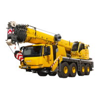
Display of the slewing ranges
The RCL display represents the four enabled
slewing ranges
1
to
4
in a diagram with four
regions.
The maximum permissible working radius (5)
is shown for each region.
Assume that the confirmed lifting capacity table
applies to the angular ranges
– ±60° to the left/right
– ±30° to the front/rear
According to the definition for the slewing angle
display (0° to the rear) the slewing range limits
would be -30°/+30°/+150° and -150°.
The RCL display shows an angular range of
about 200°. The range of the diagram is
always in the middle corresponding to the cur-
rent slewing angle (6), for example, the
range
3
for 120°.
– When slewing
The displays (2), (3) and (6) remain at the
current position. The diagram (4) and the
displays (5) move to the left or right.
If the slewing movement would lead into a
slewing range (1) in which the maximum
permissible working radius is smaller than
the current working radius (2), then the
movement is continuously reduced until
reaching a standstill.
The speed reduction occurs in the same
manner as with the Standard slewing range
type;
à p. 11 - 52.
s
 Loading...