15 - 2 Operator’s Manual
15 Probes and Biopsy
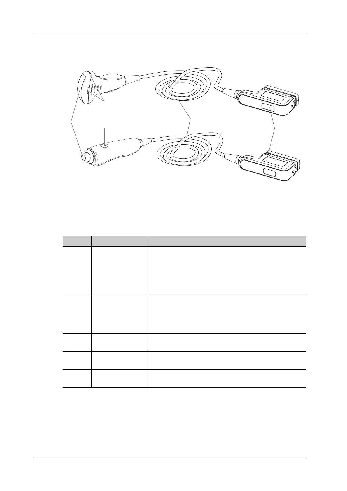
15.1.1 Probe Functions by Part
15.1.2 Orientation of the Ultrasound Image and the Probe
Head
The orientation of the ultrasound image and the probe are shown as below. The “M” side of the
ultrasound image on the monitor corresponds to the mark side of the probe. Check the orientation
before the examination.
No. Item Description
1. Probe head Converts the electrical signal into an ultrasonic signal,
focusing the sound beams in a given direction; meanwhile, it
receives the reflected ultrasonic signal and converts it into an
electrical signal for transmission over the cable. The lens on
the surface is the acoustic lens. Apply ultrasound gel on the
acoustic lens for correct operation.
2. Needle-guided
bracket fix tabs and
grooves
Provides mounting support of the needle-guided bracket.
NOTE:
This structure of probes in the figure above may vary with
the matched needle-guided brackets.
3. Trigger button and
indicator
Press to start ViTE acquisition, and indicates the probe press
level.
4. Probe cable Transmits electrical signals between the probe body and
connector.
5. Probe connector Connects the probe and cable to the ultrasonic diagnostic
system.
 Loading...


