V Series Operating Instructions 9 - 15
ECG – Arrhythmia Preparation and Lead Placement
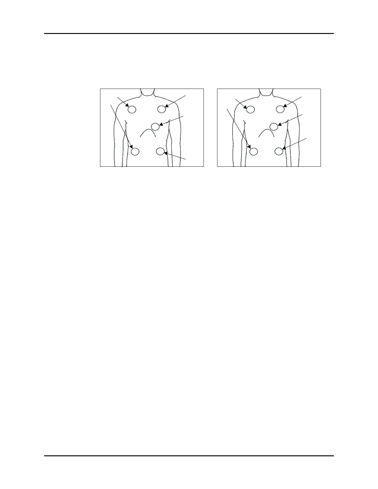
9.5.3.4 Lead Placement: Standard 5-wire Lead Sets
A 5-wire lead set can monitor seven ECG vectors (I, II, III, aVR, aVL, aVF, and V) simultaneously. The
recommended 5-wire lead placement is as follows.
FIGURE 9-9 5-wire Lead Placement (AHA) FIGURE 9-10 5-wire Lead Placement
(IEC)
• Place the RA (white) electrode under the
patient’s right clavicle, at the mid-clavicular
line within the rib cage frame.
• Place the LA (black) electrode under the
patient’s left clavicle, at the mid-clavicular
line within the rib cage frame.
• Place the LL (red) electrode on the patient’s
lower left abdomen within the rib cage
frame.
• Place the RL (green) electrode on the
patient’s lower right abdomen within the
rib cage frame.
• Place the V (brown) electrode in one of the
V-lead positions (V1 to V6) depicted in the
following section.
• Place the R (red) electrode under the
patient’s right clavicle, at the mid-clavicular
line within the rib cage frame.
• Place the L (yellow) electrode under the
patient’s left clavicle, at the mid-clavicular
line within the rib cage frame.
• Place the F (green) electrode on the
patient’s lower left abdomen within the rib
cage frame.
• Place the N (black) electrode on the
patient’s lower right abdomen within the
rib cage frame.
• Place the C (white) electrode in one of the
C-lead (C1 to C6) positions depicted in the
following section.
White
Green
Black
Brown
V Lead
(any V positi
Red
Red
Black
Yellow
White
C Lead
(any C
position)
Green
 Loading...