CCO Setup Continuous Cardiac Output (CCO) & Continuous Hemodynamics (Optional)
1 - 8 Addendum to V Series Operating Instructions
1.3 CCO Setup
1.3.1 Edwards Lifesciences Monitors
For questions regarding the use and maintenance of the Edwards Vigilance
®
, Vigilance II, the Vigileo™,
and the EV1000™ monitors, refer to its operator’s manual or contact Edwards Lifesciences
Corporation for assistance. Within the USA: (800)-424-3278, Outside the USA: (949)-250-2500.
The standard Edwards monitor measures both interm
ittent and continuous cardiac output (CCO),
and T Blood. It can also be optionally configured to measure continuous mixed venous oxygen
saturation (SvO
2
). Intermittent CO uses the bolus thermodilution method, while continuous CO uses
a pulmonary artery catheter to introduce small pulses of energy into the blood and then record the
blood temperature. SvO
2
is measured by a spectrophotometric technique that uses light emitting
diodes to transmit light in the red and infrared spectra through an optical fiber in a pulmonary artery
catheter to the blood.
The V 12/V 21 can
interface with the Edwards Vigilance
®
, Vigilance II, the Vigileo™ and the EV1000™.
This enables CO, T Blood and SvO
2
data to be displayed and trended at the V 12/V 21, while
providing alarm control for these parameters. The V 12/V 21 uses T Blood data from Edwards monitor
to derive ΔT which can also be displayed and trended, as well as providing alarm control.
At the V 12/V 21, th
e CO value is divided by the patient’s BSA (Body Surface Area) to calculate and
display a corresponding cardiac index (CI). The BSA is determined from the patient’s height and
weight as entered in the V 12/V 21.
1.3.2 Connecting to an Edwards Monitor
The following are needed to connect the V 12/V 21 to an Edwards monitor:
• Vigilance
®
, Vigilance II, Vigileo™, or EV1000™
• One serial cable
NOTE: Use the serial cable supplied with the Edwards monitor to interface
with the VDI module.
• One VDI module
• One 1x slot in the V Hub or Integrated V Hub
NOTE: Refer to "Module Status Dialog" on page 5-2 in the V Series Operating
Instructions for additional information about 1x modules.
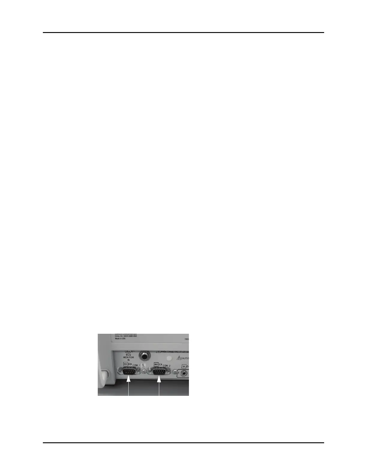
1. Connect the serial cable to an available COM port (as shown in FIGURE 1-5) on the back side of
an Edwards monitor.
FIGURE 1-5 Example COM Port (Vigilance monitor shown in this example)
2. Insert the VDI module into the V Hub or Integrated V Hub.