8 Operation
Maschinenfabrik Reinhausen GmbH 2020198 3587317/21 ENTAPCON
®
Circuit breaker configuration
You can set the assignment of circuit breakers to the individual node points.
The device uses the assignment to detect which transformers are connected
in parallel with one another.
Upon delivery, the device is configured in accordance with your order. Note
the connection diagram provided for the configuration.
Note the following conventions for the circuit breaker configuration:
▪ Nodes 1...16 correspond to the secondary side of the transformers ac-
cording to the devices with CAN addresses 1...16 (node 1 = CAN address
1, node 2 = CAN address 2, etc.).
▪ You can use nodes 17...48 to configure the connection of the circuit
breakers on the secondary side.
▪ Nodes 49...64 correspond to the primary side of the transformers accord-
ing to the devices with CAN addresses 1...16 (node 49 = CAN address 1,
node 50 = CAN address 2, etc.).
▪ You can use nodes 65...80 to configure the connection of the circuit
breakers on the primary side.
If you assign the node A = 0 and node B = 0 node pair to a circuit breaker,
the circuit breaker is deactivated for topology recording.
You have to assign a node pair to every circuit breaker.
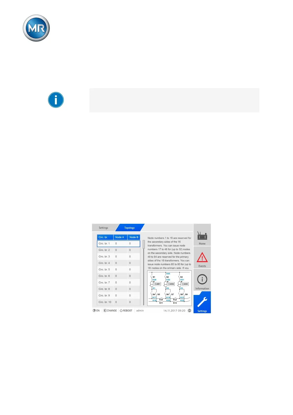
1. Go to Settings > Topology.
Figure136: Configuring the topology