8 Operation
Maschinenfabrik Reinhausen GmbH 2020 2333587317/21 EN TAPCON
®
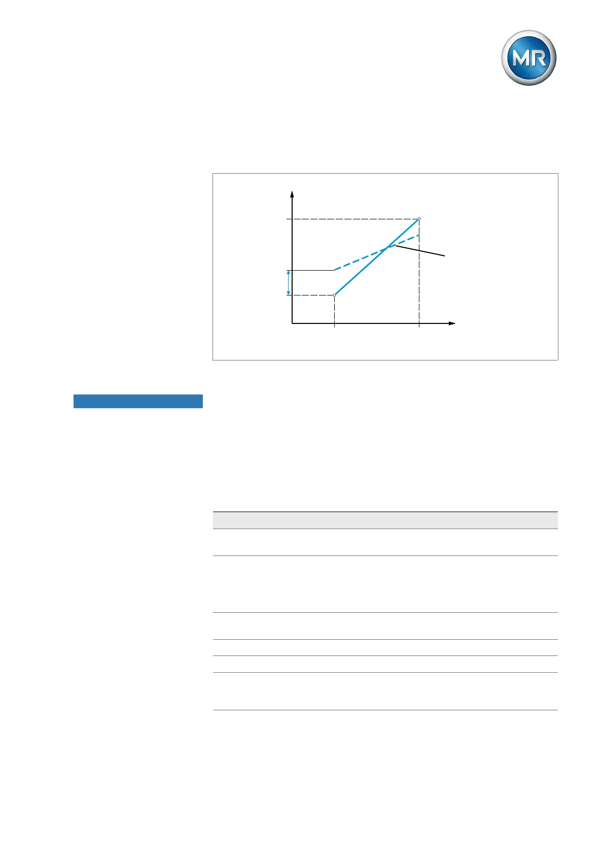
Correction factor and offset Setting a correction offsets systematic errors of the analog signals. The cor-
rection is determined by multiplying a factor by the sum of the offset. The
minimum and maximum values of the function values apply as a limit value
for the correction. There is no limit for the correction offset.
Max.
Min.
Measured variable
Max.Min. Analog signal
Correction factor
Correction offset
Figure164: Analog signal with linear characteristic curve, correction factor <1 and correction off-
set
NOTICE
Damage to the device and sensors!
Incorrectly connected and configured analog inputs/outputs may result in
damage to the device and sensor.
► Follow information about connecting analog sensors.
► Configure analog inputs and outputs according to the connected sensors.
The following information is displayed in tabular form for configuring the ana-
log inputs and outputs. Grayed-out elements cannot be changed.
Property Options
Function Function of the analog input (I: ...) or the analog output
(O: ...). You can adjust the designation.
Signal type Select signal type of analog sensor or deactivate analog
output.
▪ 4...20mA
▪ PT100-2/3/4, PT1000-2/3/4
Card/channel Select the slot and channel of the analog sensor. Note the
connection diagram supplied.
Unit
1)
Set the unit of the signal.
Decimal places
1)
Set up to three decimal places.
Minimum/maximum
value
Set the minimum and maximum values of the sensor, e.g.
with a 4...20mA signal, the corresponding measured
value for 4mA and the corresponding value for 20mA.