Introduction
25
ProSecure Unified Threat Management (UTM) Appliance
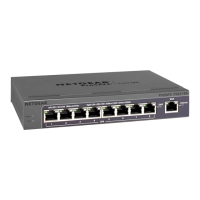
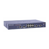
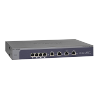
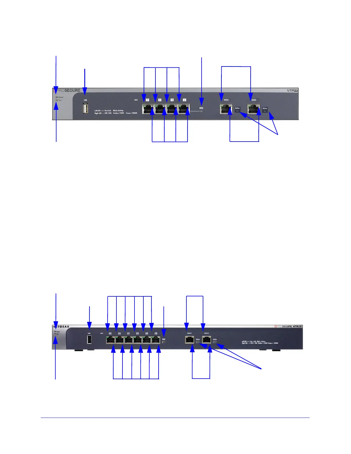
Figure 3. Front panel UTM25
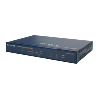
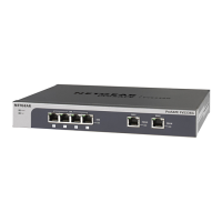
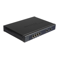
Front Panel UTM50
Viewed from left to right, the UTM front panel contains the following ports (see the following
figure, which shows a multiple WAN port model, the UTM25):
• One nonfunctioning USB port. This port is included for future management
enhancements. The port is currently not operable on the UTM.
• LAN Ethernet ports. Six switched N-way automatic speed negotiating, Auto MDI/MDIX,
Gigabit Ethernet ports with RJ-45 connectors.
• WAN Ethernet ports. Two independent N-way automatic speed negotiating, Auto
MDI/MDIX, Gigabit Ethernet ports with RJ-45 connectors.
The front panel also contains three groups of status indicator LEDs, including Power and Test
LEDs, LAN LEDs, and WAN LEDs, all of which are explained in detail in Table 2 on page 28.
In addition, the front panel provides some LED explanation to the right of the WAN ports.
Figure 4. Front panel UTM50
Power LED
Test LED
Left LAN LEDs
Right LAN LEDs
DMZ LED
Left WAN LEDs
Right WAN LEDs
Active
WAN
USB port
LEDs
Power LED
Test LED
Left LAN LEDs
Right LAN LEDs
DMZ LED
Left WAN LEDs
Right WAN LEDs
Active
WAN
USB port
LEDs