Introduction
28
ProSecure Unified Threat Management (UTM) Appliance
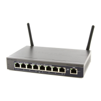
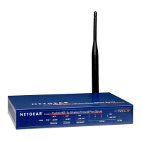
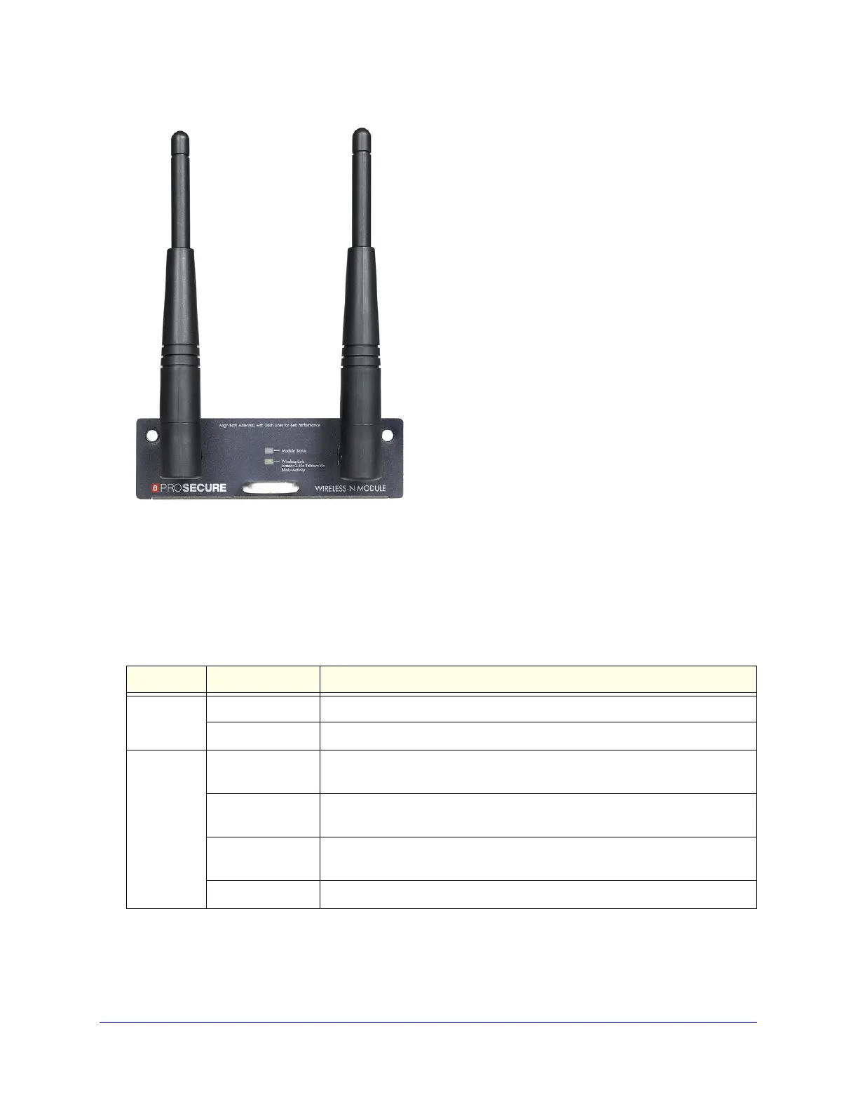
Figure 8. UTM9SWLSN wireless module
LED Descriptions, UTM5, UTM10, UTM25, UTM50, and
UTM150
The following table describes the function of each LED.
Table 2. LED descriptions UTM5, UTM10, UTM25, UTM50, and UTM150
LED Activity Description
Power LED On (green) Power is supplied to the UTM.
Off Power is not supplied to the UTM.
Test LED On (amber) during
startup
Test mode. The UTM is initializing. After approximately 2 minutes, when the
UTM has completed its initialization, the Test LED goes off.
On (amber) during
any other time
The initialization has failed, or a hardware failure has occurred.
Blinking (amber) The UTM is writing to flash memory (during upgrading or resetting to
defaults).
Off The UTM has booted successfully.