Introduction
31
ProSecure Unified Threat Management (UTM) Appliance
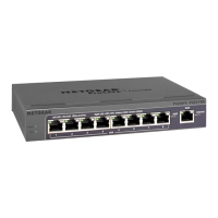
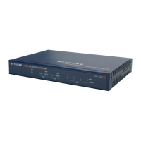
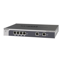
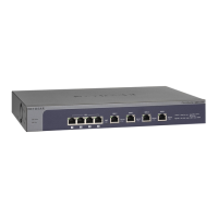
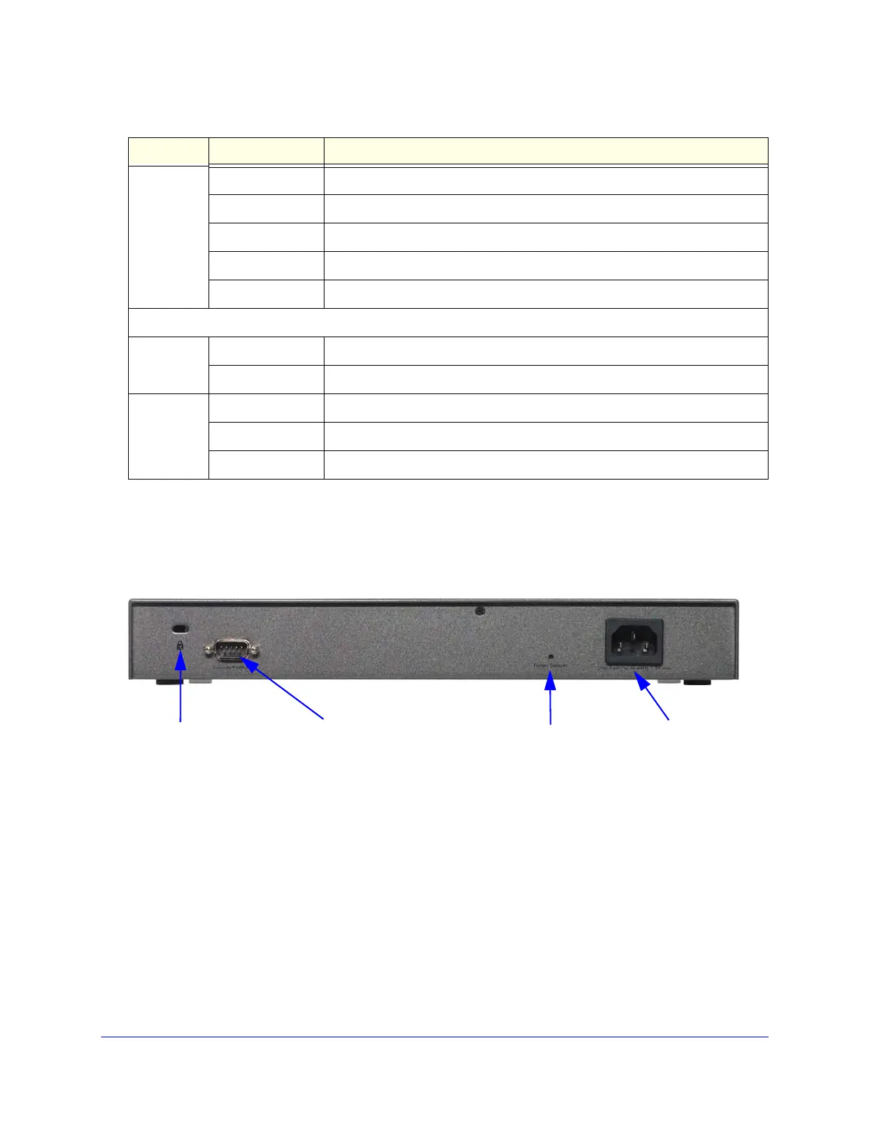
Rear Panel UTM5, UTM10, and UTM25
The rear panel of the UTM includes a cable lock receptacle, a console port, a factory default
Reset button, and an AC power connection.
Figure 9. Rear panel of the UTM5, UTM10, and UTM25
Viewed from left to right, the rear panel of the UTM5, UTM10, and UTM25 contains the
following components:
1. Cable security lock receptacle.
2. Console port. Port for connecting to an optional console terminal. The port has a DB9 male
connector. The default baud rate is 9600 K. The pinouts are (2) Tx, (3) Rx, (5) and (7) Gnd.
3. Factory default Reset button. Using a sharp object, press and hold this button for about
8 seconds until the front panel Test LED flashes to reset the UTM to factory default settings.
Configuration changes are lost, and the default password is restored.
4. AC power receptacle. Universal AC input (100–240 VAC, 50–60 Hz).
Wireless
Link LED
Off The wireless access point is not enabled.
On (green) The wireless access point is enabled in 2.4-GHz operating mode.
Blinking (green) There is wireless activity in 2.4-GHz operating mode.
On (yellow) The wireless access point is enabled in 5-GHz operating mode.
Blinking (yellow) There is wireless activity in 5-GHz operating mode.
xDSL module
Module
Status LED
Off The module is enabled or has a link the the telephone line.
On (green) The module either is not enabled or has no link to the telephone line.
Link LED Off The xDLS port has no Internet connection.
On (green) The xDSL port functions in ADSL mode.
On (yellow) The xDSL port functions in VDSL mode.
Table 3. LED descriptions UTM9S (continued)
LED Activity Description
Security lock
receptacle
Console port
Factory Defaults
AC power
receptacle
reset button