Oki Data CONFIDENTIAL
43967002TH Rev. 1
317 /
7. Troubleshooting
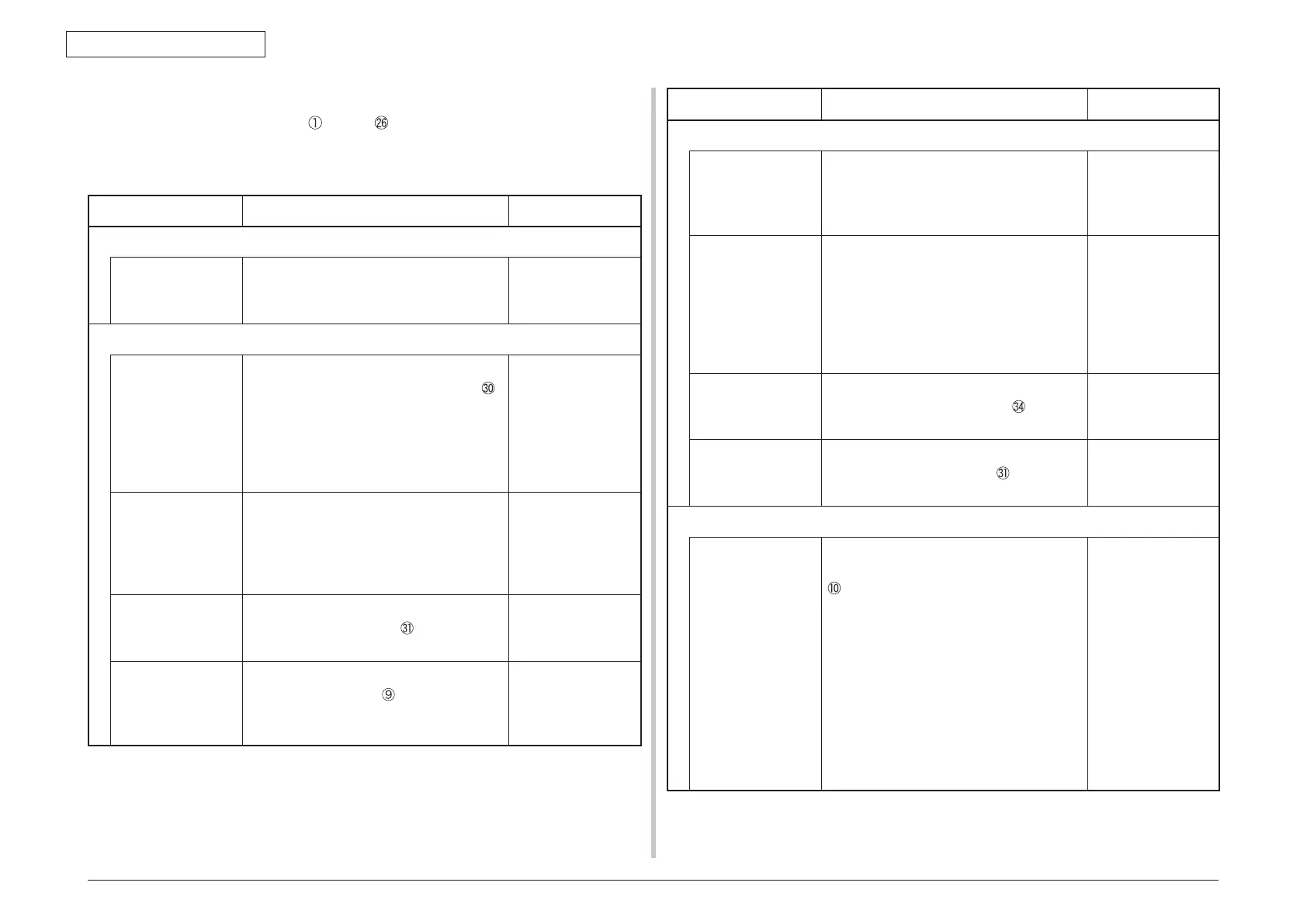
7.5.2.(1) LCD display error
Memo For the numbers from through after name of the respective connectors,
refer to 7.5.2.(19) “Wiring diagram”.
(1-1) LCD does not display an
ything.
Check item Check work
Action to be taken at NG
(1-1-1) Check the fuse
F2, F3 and F4
(fuses) on MZA
PCB
Check if F2 or F3 or F4 has blown out or
not.
Replacement of F2,
F3, F4 or MZA PCB.
(1-1-2) Check the system connection
C
onnection between
the low voltage
power supply unit
and the MZA PCB
Check if the cable from the low voltage
power supply to the POWER connector
of the MZA PCB is normally connected or
not. Check if the connector is connected in
the half-way only or not, and check if the
connector is inserted in a slanted angle or
not.
Re-connect the
cable normally.
Cable assembly
connecting the
low voltage power
supply unit and the
MZA PCB
Check if any open-circuit or peeling-off
of sheath has occurred or not throughout
the cable. Check if the cable assembly
is defective such as internal wires are
disconnected or not.
Replace the cable
with the normal
cable.
Power supply to
MAZ PCB and
scanner
Check that cable is connected normally
to the SCPOW connector
of MZA PCB.
Check for secure coupling of connectors.
Re-connect the
cable normally.
FFC connecting the
PU PCB and the CU
PCB
Check that 12-conductor FFC is connected
to the CUIF connector
of the P PCB.
Check the CU PCB side in the same
manner.
Replace the low
voltage power
supply.
Check item Check work
Action to be taken at NG
(1-1-3) Check the peripherals of the power supplies
Primary AC power
source that is
connected to the
printer.
Check the supplied voltage of the AC
power source.
Supply the AC
power.
Voltage setting of
the lower voltage
power supply unit
(100V system/230V
system)
Measure the AC voltage supplied.
Check the power voltage setting of the
equipment in use.
(Check the shorting plug that is used for
selection of the voltage power supplies.)
Shorting plug is Used/Not used = 100V
system/230V system.
Set the low voltage
power supply
setting.
5V power that is
supplied to the MZA
PCB.
Check 5V power at pin-1 and 24V power at
pin-6 of the POWER connector
of MZA
PCB.
Replace the low
voltage power
supply.
5V power that is
supplied to the
scanner
Check 24V power at pin-1, and 5V power
at pin-5 of the CN connector
of A PCB.
Replace F5 or the
P6X PCB.
(1-1-4) Check that power supply circuit has no short-circuit.
5V or 24V power
supply that is
supplied to the PU
PCB
Check that power supply circuit has no
short-circuit at the POWER connector pin
of the POWER PCB.
Pin-4, -5, -6: 24V
Pin-7: 5V
Pin-8: 0VL
Pin-1, -2, -3: 0VP
If any voltage does not appear and short-
circuit is detected, locate the source of
the short-circuit as follows. Disconnect the
cables that are connected to the PU PCB
one cable after another until location of the
short-circuit is found out.
Replace the part
causing short-
circuit.
 Loading...