Oki Data CONFIDENTIAL
43967002TH Rev. 1
344 /
7. Troubleshooting
Note! Toner sensor operation check method using the SWITCH SCAN function of
th
e self-diagnostic mode.
(1) H
ow to check operation of the toner sensor at the printer side.
1. Status change of the toner sensor can be checked from the Operator
Panel using the self-diagnostic mode. First, switch the display to the
Operator Panel display. For the method of switching the display to the
Operator Panel display, refer to item 5.3.2.3 Switch Scan Test.
2
. Re
move the ID unit and the toner cartridge (TC) from a printer. There
is a window inside a printer opposing the ID side when viewed from
the front of a printer. The toner sensor is located inside the window.
3. Pl
ace a white paper 3 mm away from the sensor window. The white
paper should be placed in the manner of opposing the toner sensor.
4. Wh
en light is reflected by a white paper so that incident light falls on
the toner sensor, the Operator Panel display shows “L”. When the
paper is moved so that any light is not reflected by the paper so that
the incident light does not reach the toner sensor, “H” is displayed on
the Operator Panel.
5
. If
the Operator Panel display toggles between “H” <-> “L” as a paper
is flipped in front of the toner sensor, it indicates that the toner sensor
and the related system of the printer are working normally.
Act
ion to be taken at NG
• Clean surface of the toner sensor to remove the stains due to residual
toner and paper dust.
• Che
ck the connection condition of the FFC cable at the PU main PCB
(PU) and at the toner sensor PCB (PRZ).
• Per
form the operation check again. If the situation is not improved
and remains unchanged, replace the PU main PCB (PU) or the toner
sensor PCB (PRZ).
(2) H
ow to check operation of the toner sensor at the toner cartridge (TC)
side
1. To the position where the toner sensor is confirmed to be operating
normally in the printer itself by the above paragraph (1), install the
TC and the ID unit to check operations by observing display on the
Operator Panel.
2. If the ID unit works normally, the display on the Operator Panel will
toggle between “H” <-> “L” in synchronism with movement of the silver
reflector plate that is located on the side of the ID.
A
ct
ion to be taken at NG
• Check operation condition of the respective ID motors by using the
Motor & Clutch Test of the self-diagnostic mode.
• Cle
an surface of the silver reflector plate on the side of ID to remove
stains. (Stain due to toner or paper dust).
• Rep
lace the TC of different color and the ID unit as a pair.
If a satisfactory operation is attained by using a pair of TC of different
color and the ID unit, replace the TC or replace the ID unit.
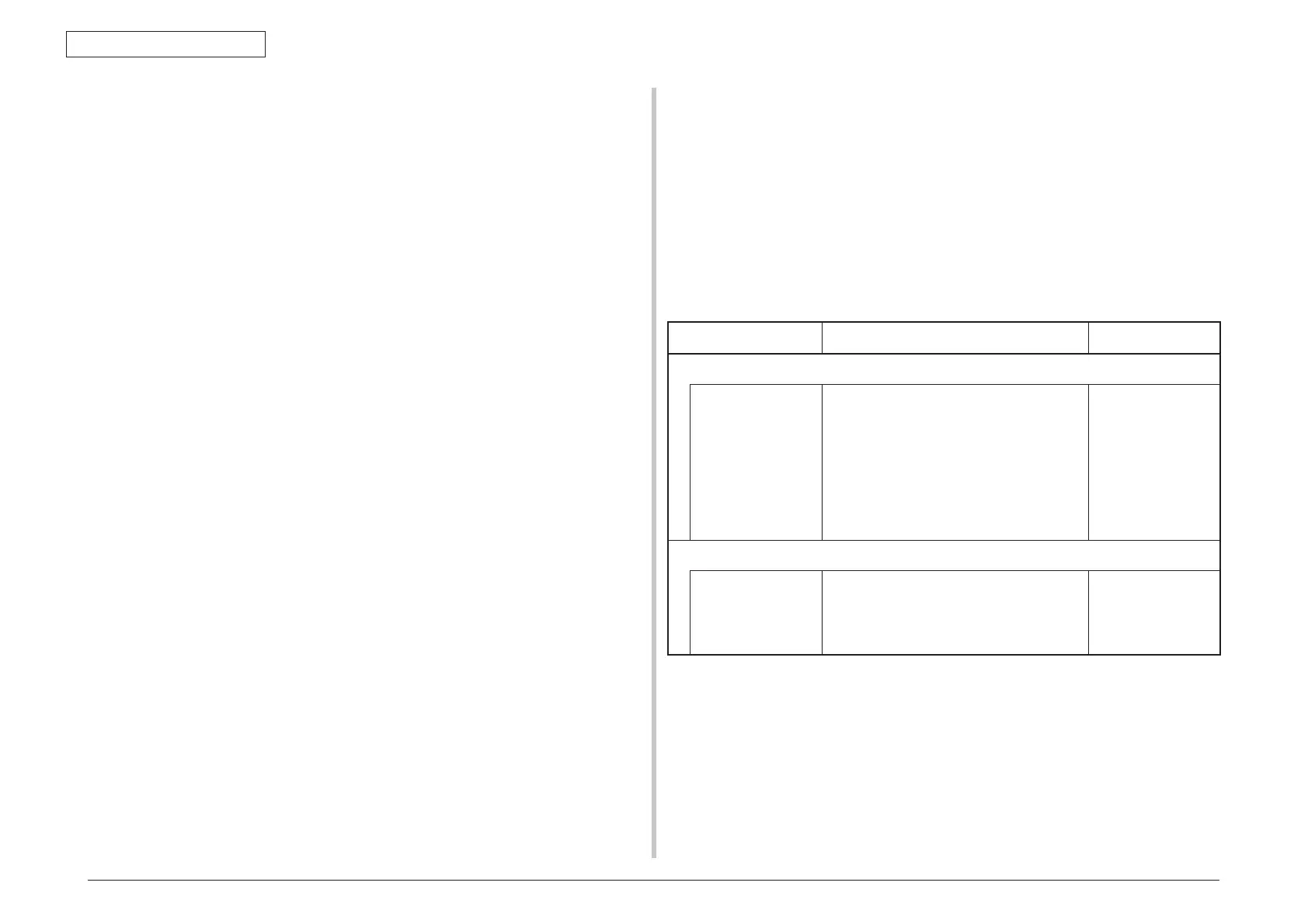
(16-3) Error caused by the def
ective mechanism
Check item Check work
Action to be taken at NG
(16-3-1) Mechanical load applied to the ID unit
ID unit Check if a heavy mechanical load is being
applied to the ID unit due to breakage of
the waster toner belt, or not.
Replace the ID unit.
If any attempt of
using new ID unit
as a trial is going to
be made, be sure
to use the System
Maintenance Menu
FUSE KEEP MODE.
(16-3-2) Motor operating condition
ID motor Confir
m that the respective ID motors work
normally or not by using the Motor & Clutch
Test of the self-diagnostic mode.
Check if any extra load exists or not.
Replace the PU
PCB or ID motor
 Loading...