43967002TH Rev.1
44 /
Oki Data CONFIDENTIAL
2. Theory of Operation
2.3 Image scanning process
2.3.1 Structure and process of RADF
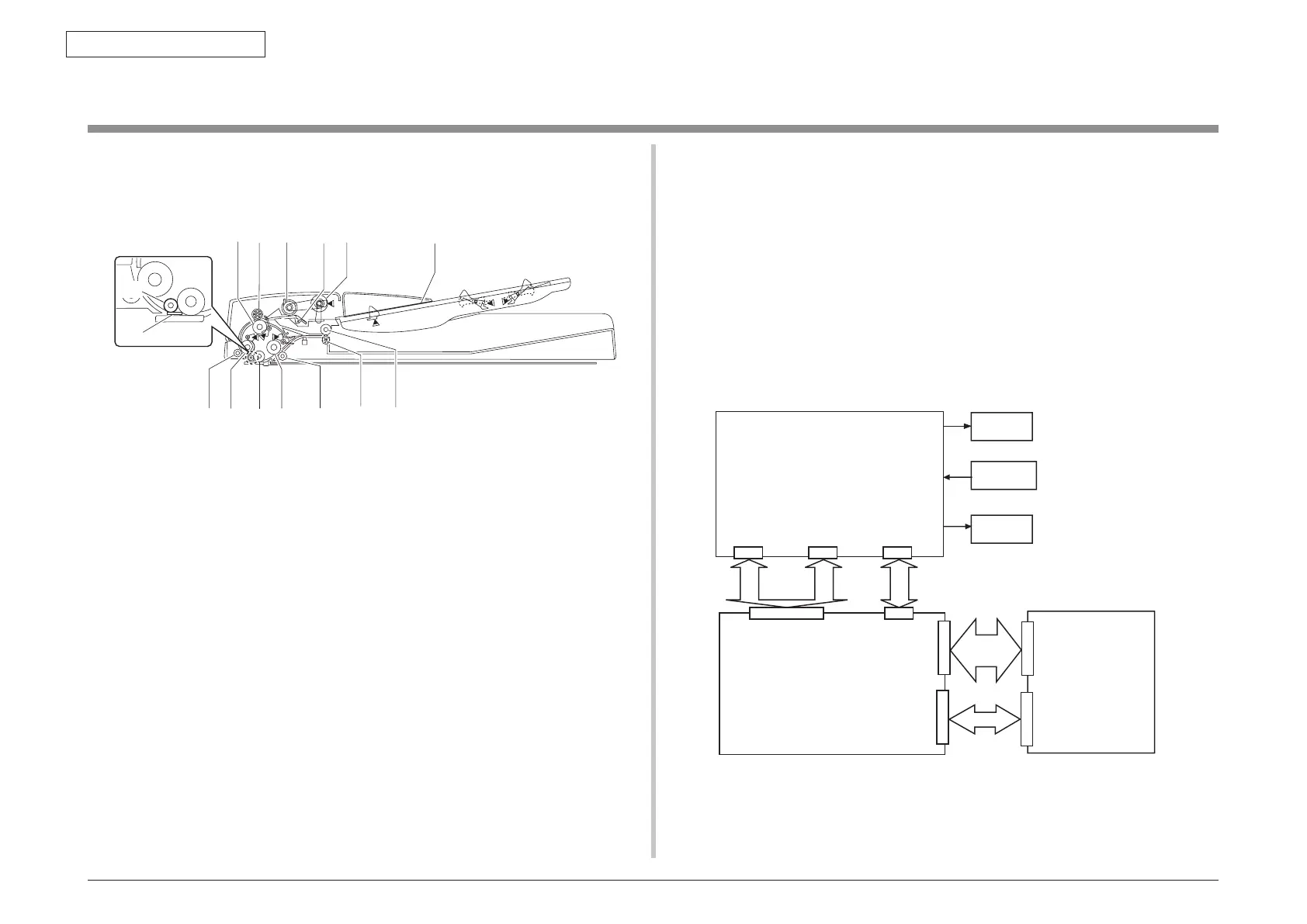
2.3.1.1 Cross-section view
[1] Lower regist roller
[2] Upper regist roller
[3] Separator roller
[4] Separator pad
[5] Feed paper roller
[6] Document feed tray
[7] Unloading paper inversion upper roller
[8] Unloading paper inversion lower roller
[9] Read roller, 2 pieces
[10] Read roller 2
[11] Platen roller
[12] Read bearer
[13] Read roller 1
[14] Read roller, 1 piece
[15] White sheet
[1] [2] [3] [4] [5]
[6]
[9]
[7]
[10][11][13][14]
[8]
[12]
[15]
2.3.1.2 Electrical configuration
Electrical circuit configuration
Electrical control of the MFP is executed by the reader controller circuit PCB and the image
processor circuit PCB. The ASIC of the reader controller circuit PCB and the ASIC of the
image processor circuit PCB interpret the input signals that are supplied from sensors and
the signals that are supplied from the externally connected equipment. The ASICs output the
signals that drive the DC load devices such as motor and solenoid in accordance with the
specified timings. The ADF driver circuit PCB and the reader controller circuit PCB do not
contain the memory area. The data such as service mode data is stored in the processor
circuit PCB.
Motor
ADF driver PCB
Scanner RADF PCB
Solenoid
Sensor
+3.3V
Main PCB
CN1 CN2
+24V
P150P151
CN10
P140A
P1408
P14A
P14B