Oki Data CONFIDENTIAL
43967002TH Rev. 1
318 /
7. Troubleshooting
(1-2) From the startup screen after power-on:
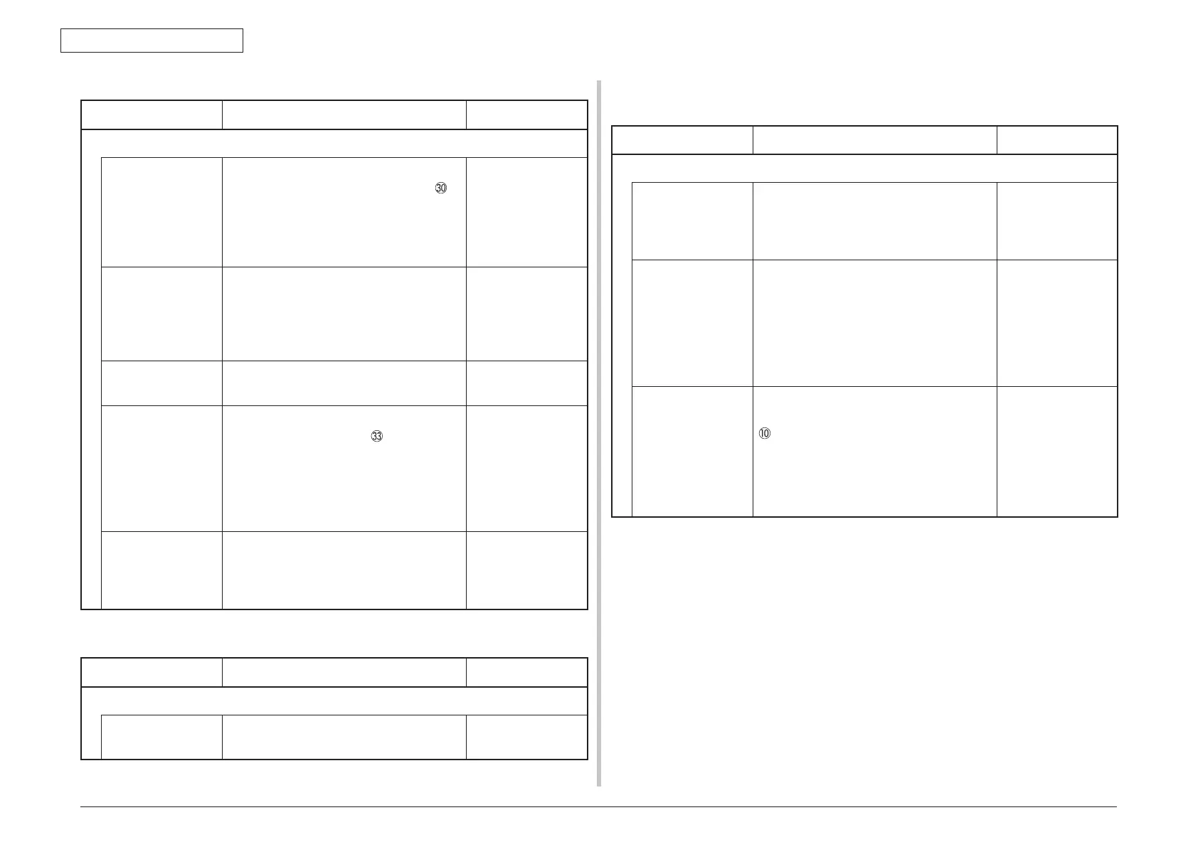
Check item Check work
Action to be taken at NG
(1-2-1) Check the system connection
Connection between
the low voltage
power supply unit
and the MZA PCB
Check if the cable from the low voltage
power supply to the POWER connector
of
the MZA PCB is normally connected or not.
Check if the connector is connected in the
half-way only or not, and check if the
connector is inserted in a slanted angle or not.
Re-connect the
cable normally.
Cable assembly
connecting the
low voltage power
supply unit and the
MZA PCB
Check if the cable has open circuit or not.
Check if sheath of the cable has not peeled
off or not.
Check if the cable assembly is defective such
as internal wires are disconnected or not.
Replace the cable
with the normal
cable.
Connection of the
MZA scanner
Check that the scanner unit connector of
the MZA PCB is normally connected.
Re-connect the
cable normally.
FFC connecting the
MZA PCB and the
TB2 PCB
Check that the 11-conductor FFC is
connected to the conector
CU PCB.
Check that the connection with the MZA
PCB is normal. Check if the connector
is connected in the half-way only or not,
and check if the connector is inserted in a
slanted angle or not.
Re-connect the
cable normally.
Direct connection
between the TB2
PCB and the MZA
PCB
Check that the MZA PCB is not installed in
the wrong position by the visual check.
Re-install the MZA
PCB into the correct
position.
(1-3) Error messages related to Operator Panel are displayed.
Check item Check work
Action to be taken at NG
(1-3-1) Error message
Error message Check the error contents by referring to the
Error Message List.
Follow the
instruction.
7.5.2.(2) Abnormal operations of printer after the power is turned on
(2-1) Any operation does not start at all
Check item Check work
Action to be taken at NG
(2-1-1) Check the peripherals of the power supplies
Primary AC power
source that is
connected to the
printer.
Check the supplied voltage of the AC
power source.
Supply the AC
power.
Voltage setting of
the lower voltage
power supply unit
(100V system/230V
system)
Measure the AC voltage supplied.
Check the power voltage setting of the
equipment in use.
(Check the shorting plug that is used for
selection of the voltage power supplies.
[CN6]) Shorting plug is Used/Not used =
100V system/230V system.
Set the low voltage
power supply
setting.
5V power and 24V
power that are
supplied to the PU
PCB.
Check that power supply circuit has no
short-circuit at the POWER connector pin
of the POWER PCB.
Pin-4, -5, -6: 24V
Pin-7: 5V
Pin-8: 0VL
Pin-1, -2, -3: 0VP
Replace the low
voltage power
supply unit.
 Loading...