43967002TH Rev.1
241 /
Oki Data CONFIDENTIAL
5. Maintenance Menu
5.10.3.3 Switch scan test
This self-diagnostic menu is used to check the input sensor and switch.
1. Enter the self-diagnostic mode (Level 1) and press the (2) key and (8) key until
"SWITCH SCAN” is displayed in the top of the screen. Then, press the (6) key.
(The (2) key increments the test item and (8) key decrements the test item.)
SWITCH SCAN
2. Press the (2) key or the (8) key until the item that corresponds to the unit which
is going to be tested is displayed in the bottom of the screen. (The (2) key
increments the item and (8) key decrements the item.)
3. When
the (8) key is pressed, the test is started. The corresponding unit name
and current status are displayed.
PAPER ROTE:PU
1=H 2=L 3=H 4=L
Op
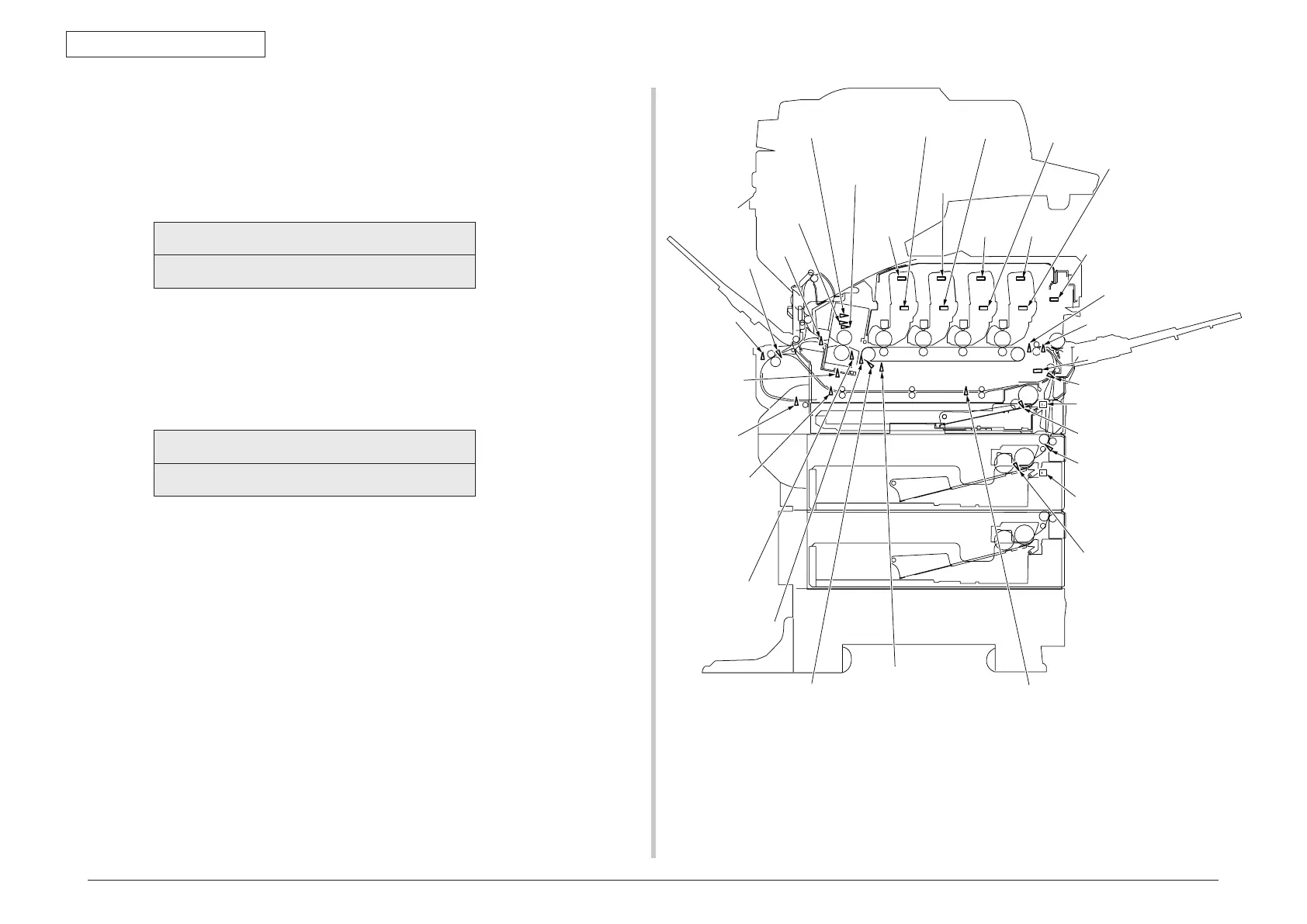
erate the respective units. (Fig. 5-1) The display is shown on the
corresponding LCD screen. (Display is different depending on sensor. For
details, refer to Table 5-3.)
4. When the (#) k
ey is pressed, screen returns to the item 2 status.
5. Repeat items 2 to 4 as required.
6. To exit the test, press the (4) key. (Screen returns to the item 2 condition.)
Entrance sensor 1
Entrance sensor 2
Write sensor
Unload
sensor
Tray 1 paper end sensor
Color registration error sensor L
Color registration error sensor R
Density sensor
Belt thermistor
Toner sensor K
FID
antenna K
RFID
antenna Y
RFID
antenna M
RFID
antenna C
Toner sensor Y
Toner sensor M
Toner sensor C
Fuser thermistor,
Upper sensor, side
Heater frame
thermistor
Fuser thermistor, Lower
ID Up/Down sensor
Temperature humidity sensor
Duplex
input sensor
Duplex cover
open sensor
Duplex
bottom sensor
Fuser
release
sensor
Duplex rear sensor
Duplex front sensor
Tray 2 entrance sensor
2nd tray size setting switch
1st tray size setting switch
Tray 2 paper end sensor
Cover open switch
Fuse entrance sensor
Fig. 5-1 Switches and sensors locations