viii
Introduction
F3SG-R
User’s Manual
Install F3SG-R so that it is not affected by reflective surfaces. Failure to do so may hinder
detection, resulting in serious injury. For an installation distance from reflective surfaces, see 4-1-
3. Distance from Reflective Surfaces.
When using more than 1 set of F3SG-R in adjacent areas, the emitter of one F3SG-R may
interfere with the receiver of the other, causing the safety functions to stop working properly.
Install and configure them so that mutual interference does not occur.
Make sure that foreign material such as water, oil, or dust does not enter the F3SG-R or the
connector while the cap or the cover of the DIP Switch is removed.
To change the response time, calculate the safety distance based on the setting. Otherwise, the
machine may not stop before a person reaches the hazardous part, resulting in serious injury.
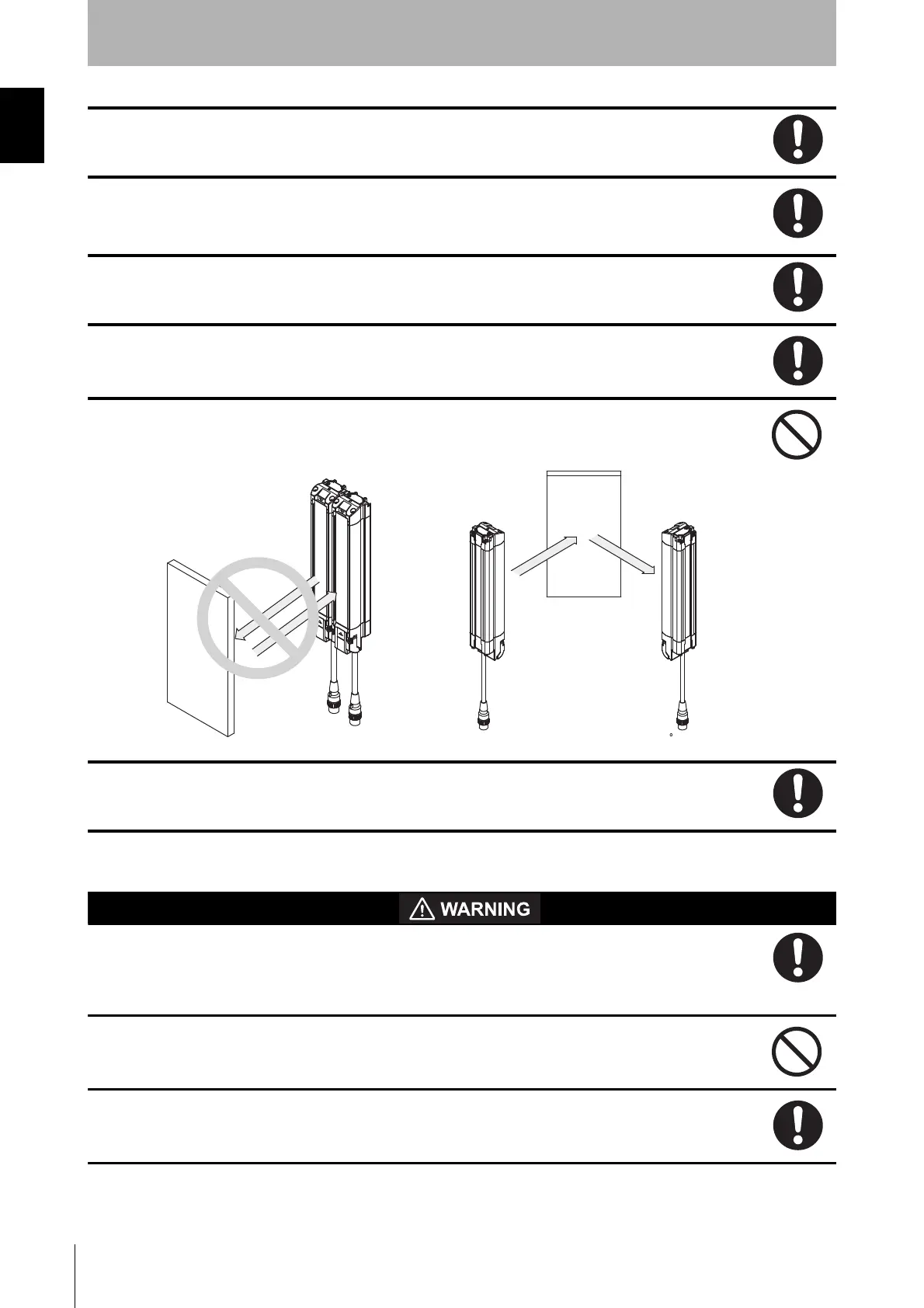
Do not use the sensor system with mirrors in a retro-reflective configuration as shown
below.Doing so may hinder detection. It is possible to use mirrors to alter the detection zone to a
90-degree angle.
Perform an inspection for all F3SG-R as described in Chapter 6 Checklists. When using cascade
connections, perform inspections for every connected F3SG-R.
For wiring
When using the PNP output, connect the load between the output and 0 V line. When using the
NPN output, connect the load between the output and +24 VDC line. Connecting the load
between the output and a different power supply line from the above will result in a dangerous
condition because the operation mode of safety output is reversed to "Dark-ON".
When using the PNP output, do not ground +24 VDC line. When using the NPN output, do not
ground 0 V line. Otherwise, a ground fault may turn the safety output ON, resulting in a failure of
stopping the machine.
Configure the system by using the optimal number of safety outputs that satisfy the requirements
of the necessary safety category.
Reflector
Reflector
Position with retro-reflection
Position with detection zone bent at 90

 Loading...


