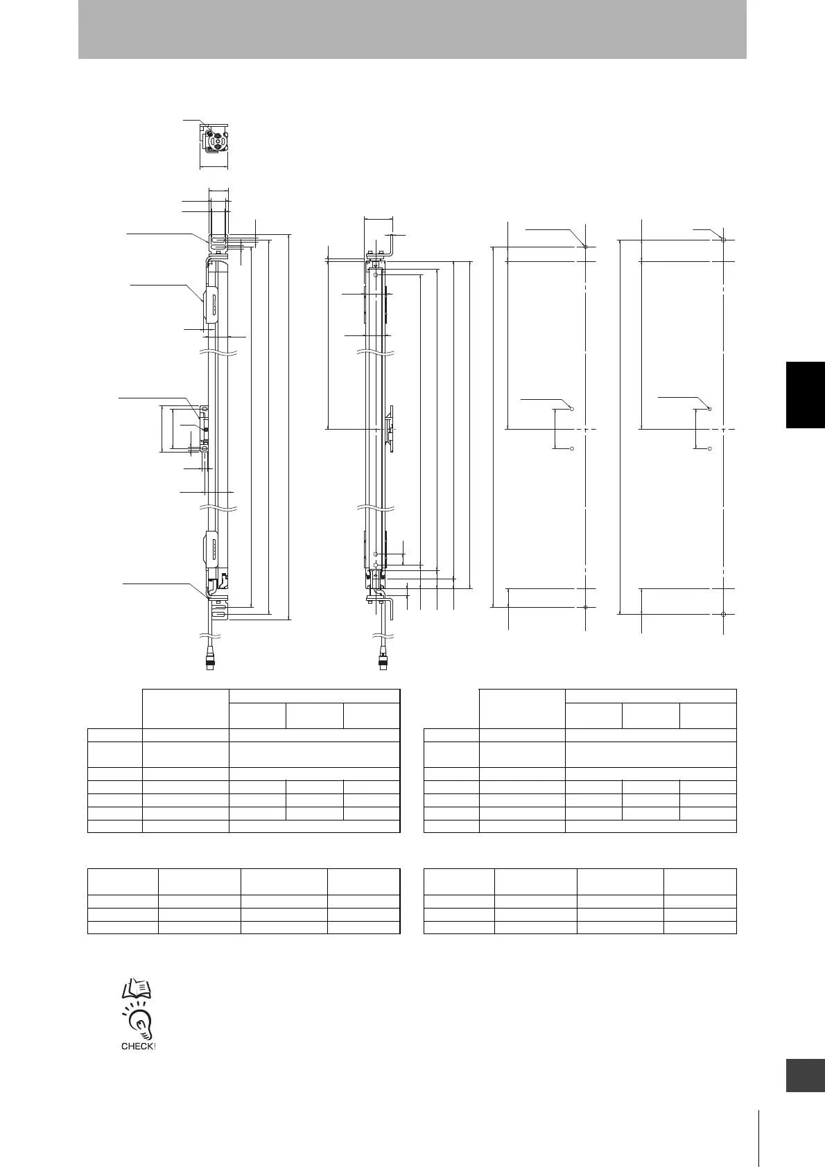
4-4-3-3. Mounting with Top/Bottom Adjustable Brackets (F39-LGTB)
wall surface. The angle adjustment range of the Top/Bottom Adjustable Brackets is ±22.5°. The angle adjustment range
Top/Bottom
Adjustable Bracket
(F39-LGTB)
Top/Bottom
Adjustable Bracket
(F39-LGTB)
Standard
Adjustable Bracket
(F39-LGA)
Backside : 2-S3
2-M5 or M6
2-M5 or M6
2-M5 or M6
C1 (Protective height for 30 mm)
C2 (Protective height for 14 mm)
<Screw for Top/Bottom Adjustable
Bracket: M5 or M6>
<Screw for Top/Bottom Adjustable
Bracket: M8>
2-M8
40.8
35
A
4
51.65
4
12
S2.5
35
23.2
26.5
35
6.5
8.2
H
I
84
9.2
6.4
72
G
9.6
2-S3
50.35
42.35
18
33
43 D
P
F
F
F
H
38.5 46.5
33.75
25.75
G
72
72
[ Unit : mm ]
F3SG-RA-30 Series
Optional
accessory not
connected
Optional accessory connected*
F39-JGR2W
F39-BT
F39-LP
F39-BTLP
Dimension A
C1+18 Same as on the left
Dimension C1
4-digit number of the type
name (Protective height)
Same as on the left
Dimension D
C1-50 Same as on the left
Dimension G
C1+77.5 C1+80.5 C1+91 C1+102.5
Dimension H
C1+103 C1+106 C1+116.5 C1+128
Dimension I
C1+122 C1+125 C1+135.5 C1+147
Dimension P
20 Same as on the left
Protective height
(C1)
Number of Top/Bottom
Adjustable Brackets*1
Number of Standard
Adjustable Brackets *1 *2
Dimension F
0270 to 1070 2 0 -
1150 to 1950 2 1 1000 mm max.
2030 to 2510 2 2 1000 mm max.
F3SG-RA-14 Series
Optional
accessory not
connected
Optional accessory connected*
F39-JGR2W
F39-BT
F39-LP
F39-BTLP
Dimension A
C2+48 Same as on the left
Dimension C2
4-digit number of the type
name (Protective height)
Same as on the left
Dimension D
C2-20 Same as on the left
Dimension G
C2+107.5 C2+110.5 C2+121 C2+132.5
Dimension H
C2+133 C2+136 C2+146.5 C2+158
Dimension I
C2+152 C2+155 C2+165.5 C2+177
Dimension P
10 Same as on the left
Protective height
(C2)
Number of Top/Bottom
Adjustable Brackets*1
Number of Standard
Adjustable Brackets *1 *2
Dimension F
0240 to 1040 2 0 -
1120 to 1920 2 1 1000 mm max.
2000 to 2080 2 2 1000 mm max.
*1. The number of brackets required to mount either one of emitter and receiver.
*2. The Top/Bottom Adjustable Bracket is not useable together with the Standard Fixed Bracket. When it is necessary to use it with another bracket, only
the combination with the Standard Adjustable Bracket is possible.
* Refer to
Connected with Optional Accessories
under 4-3-3-1. F3SG-RA Series for more information on the dimensions when optional accessories are connected to the F3SG-RA.

 Loading...


