145
F3SG-R
User’s Manual
Chapter4 Dimensions
Wiring/Installation
E
[Side Mounting]
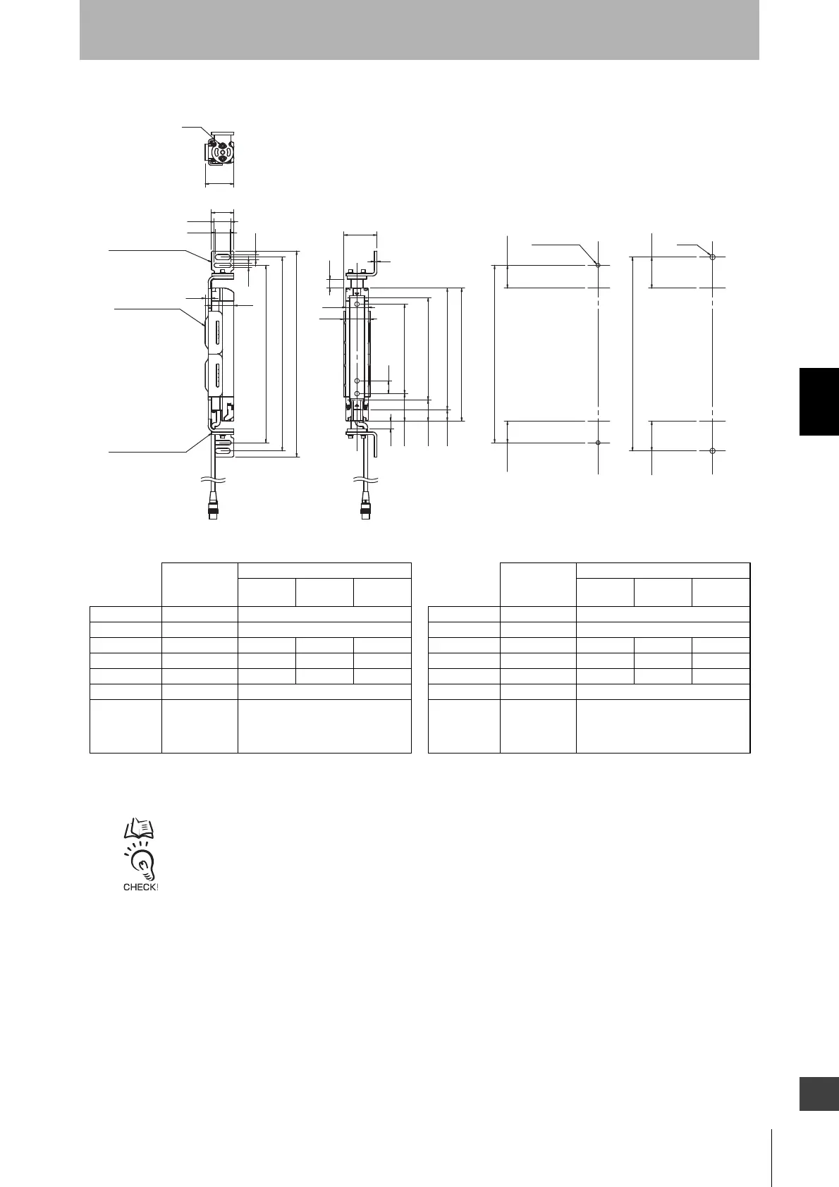
4-4-3-3. Mounting with Top/Bottom Adjustable Brackets (F39-LGTB)
- Use the brackets of specified quantities and locations according to the dimensions. The other brackets than described
above may not meet the specified ratings and performance.
- When you use the sensor in a situation where the sensor is under a load, increase the number of the brackets used.
- The Top/Bottom Adjustable Bracket and Standard Adjustable Bracket allow beam alignment after fixing the bracket to a
wall surface. The angle adjustment range of the Top/Bottom Adjustable Brackets is ±22.5°. The angle adjustment range
of the Standard Adjustable Brackets is ±15°.
2-S3
44.6
I
G
8.2
23.2
26.5
35
H
6.5
9.6
35
2-M8
208
4
14
40.8
51.65
12
35
D
33
43
P
H
48.5 46.5
35.75 33.75
G
18
C1 (Protective height for 30 mm)
C2 (Protective height for 14 mm)
Top/Bottom
Adjustable Bracket
(F39-LGTB)
Top/Bottom
Adjustable Bracket
(F39-LGTB)
Backside : 2-S3
2-M5 or M6
<Screw for Top/Bottom Adjustable
Bracket: M5 or M6>
<Screw for Top/Bottom Adjustable
Bracket: M8>
F3SG-4RA0190-30
Optional
accessory not
connected
Optional accessory connected*1
F39-JGR2W
F39-BT
F39-LP
F39-BTLP
Dimension C1 190 Same as on the left
Dimension D 140 Same as on the left
Dimension G 277.5 277.5 281 292.5
Dimension H 303 303 306.5 318
Dimension I 322 322 325.5 337
Dimension P 20 Same as on the left
Number of
Top/Bottom
Adjustable
Brackets*2
2 Same as on the left
F3SG-4RA0160-14
Optional
accessory not
connected
Optional accessory connected*1
F39-JGR2W
F39-BT
F39-LP
F39-BTLP
Dimension C2 160 Same as on the left
Dimension D 140 Same as on the left
Dimension G 277.5 277.5 281 292.5
Dimension H 303 303 306.5 318
Dimension I 322 322 325.5 337
Dimension P 10 Same as on the left
Number of
Top/B ott om
Adjustable
Brackets*2
2 Same as on the left
*1.
Refer to
Connected with Optional Accessories
under
4-3-3-1. F3SG-RA Series
for more information on the dimensions when optional accessories are connected to the F3SG-
RA.
*2. The number of brackets required to mount either one of emitter and receiver.
[ Unit : mm ]

 Loading...


