158
Chapter4 Mounting
F3SG-R
User’s Manual
Wiring/Installation
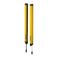
6. Power the F3SG-R on to perform beam alignment.
Move the emitter from side to side (Fig. 5) to align it to a center position where the Stable-state
indicator (STB, green) of the receiver is illuminated while checking the state of the top and bottom
beams with the Top-beam-state indicator (TOP, blue) and Bottom-beam-state indicator (BTM, blue) of
the receiver. (Fig. 6)
Next, move the receiver from side to side to align it to a center position where the Stable-state indicator
(STB, green) of the receiver is illuminated while checking the state of the top and bottom beams with
the Top-beam-state indicator (TOP, blue) and Bottom-beam-state indicator (BTM, blue) of the receiver.
The angle adjustment range of the Standard Adjustable Brackets is ±15°.
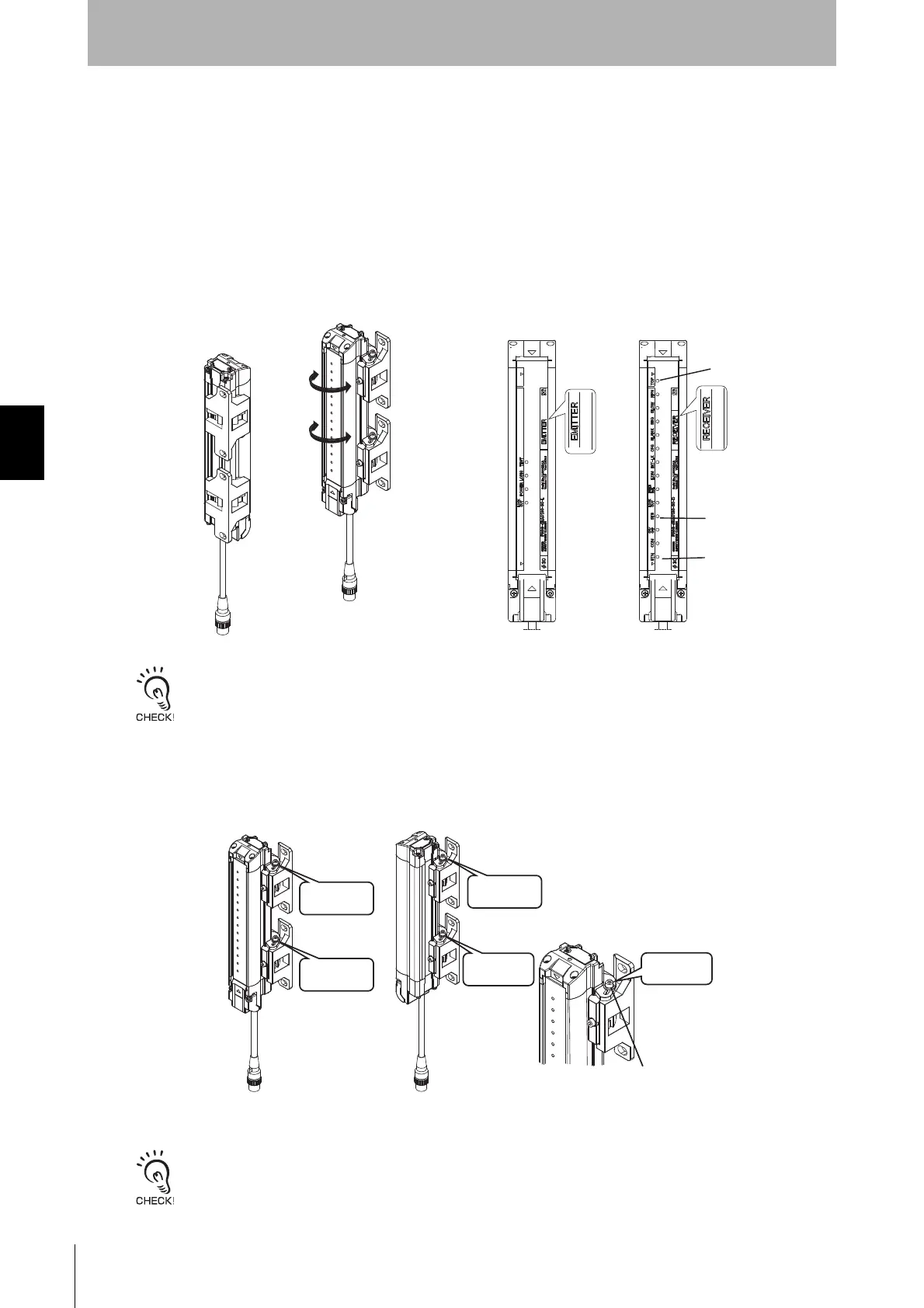
7. Securely tighten the Screw (1) to fix the Standard Adjustable Bracket to the housing of the F3SG-R.
The recommended torque to tighten the Screw (1) is 2.0 N•m. (Fig. 7)
Tightening screws with a torque that considerably exceeds the recommended torque may cause failure.
Fig. 6
<Emitter> <Receiver>
TOP(Blue)
BTM(Blue)
STB(Green)
<Backside mounting>
Securely
tighten this
<Side mounting>
<Enlarged view>
Fig. 7
Securely
tighten this
Securely
tighten this
Screw(1)
(Hexagon socket head
cap screw (M3x15))
Securely
tighten this
Securely
tighten this
 Loading...


