160
Chapter4 Mounting
F3SG-R
User’s Manual
Wiring/Installation
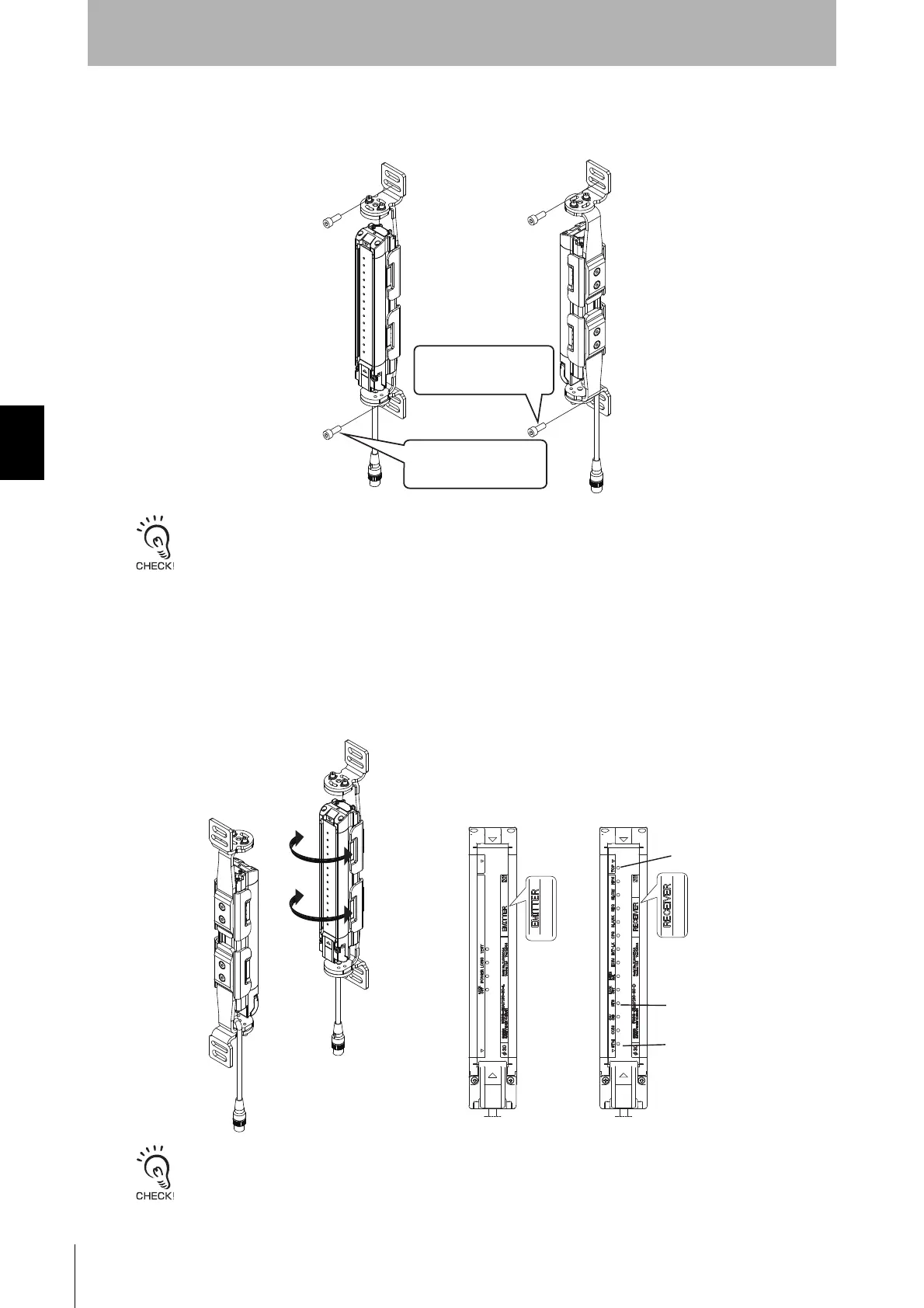
3. Securely tighten screws to fix the Top/Bottom Adjustable Bracket to the mounting position of the wall
surface. (Fig. 3)
One screw at upper and lower positions, respectively, is sufficient to fix the F3SG-R to the wall surface. Screws to mount
the brackets to the wall are not included.
4. Power the F3SG-R on to perform beam alignment.
Move the emitter from side to side (Fig. 4) to align it to a center position where the Stable-state
indicator (STB, green) of the receiver is illuminated while checking the state of the top and bottom
beams with the Top-beam-state indicator (TOP, blue) and Bottom-beam-state indicator (BTM, blue) of
the receiver. (Fig. 5)
Next, move the receiver from side to side to align it to a center position where the Stable-state indicator
(STB, green) of the receiver is illuminated while checking the state of the top and bottom beams with
the Top-beam-state indicator (TOP, blue) and Bottom-beam-state indicator (BTM, blue) of the receiver.
The angle adjustment range of the Top/Bottom Adjustable Brackets is ±22.5°.
<Backside mounting>
<Side mounting>
Fig. 3
Fix the Top/Bottom
Adjustable Bracket to the
wall surface with screws
Fix the Top/Bottom
Adjustable Bracket to the
wall surface with screws
Fig. 4 Fig. 5
<Emitter> <Receiver>
TOP(Blue)
BTM(Blue)
STB(Green)

 Loading...


