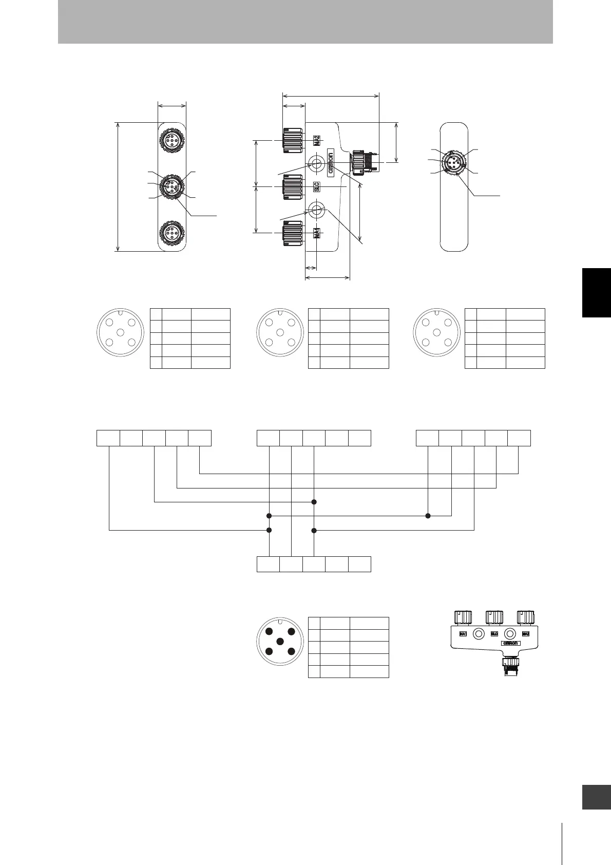
EasyManuals Logo

Omron F3SG series User Manual

Omron F3SG series
257 pages
To Next Page IconTo Next Page
To Previous Page IconTo Previous Page
Page #195 background imageLoading...
Page #195 background image
171
F3SG-R
User’s Manual
Chapter4 Wiring
Wiring/Installation
E
4-Joint Plug/Socket Connector for Emitter (F39-GCN4-L, gray, sold separately)
<Internal wiring diagram>
17
78
3
5
2
1
4
M12 x 1
5
4
1
23
M12 x 1
7
27
58.3
13.6
MA2
SLC
MA1
CN
28
28 28
24.4
2-dia. 5.5
2-dia.10
MA1
Connected to Power Cable or
Double-Ended Cable of F3SG-RA Emitter
Connected to Single-Ended Cable or
Double-Ended Cable for Emitter
Connected to Power Cable or
Double-Ended Cable of F3W-MA Emitter
Connected to Power Cable or
Double-Ended Cable of F3W-MA Emitter
5
3
21
4
Female
5
4
12
3
Male
Brown
Black
Blue
White
Yellow
+24 VDC
CFG In
0 VDC
COM+
COM-
1
2
3
4
5
Brown
Black
Blue
White
Yellow
+24 VDC
TEST
0 VDC
Not used
Not used
1
2
3
4
5
Brown
Black
Blue
White
Yellow
+24 VDC
TEST
0 VDC
Not used
Not used
1
2
3
4
5
Brown
Black
Blue
White
Yellow
+24 VDC
CFG In
0 VDC
COM+
COM-
1
2
3
4
5
5
3
21
4
Female
5
3
21
4
Female
SLC MA2
12345 12345
12345
12345
CN

Table of Contents

Other manuals for Omron F3SG series

Questions and Answers:

Question and Answer IconNeed help?

Do you have a question about the Omron F3SG series and is the answer not in the manual?

Omron F3SG series Specifications

General IconGeneral
TypeSafety Light Curtain
Protection RatingIP67
ConnectionM12 connector
Detection MethodInfrared Light
Operating Temperature-10°C to +55°C
Resolution14mm, 25mm, 40mm
StandardsEN/IEC 61496-1, EN ISO 13849-1
Power Supply Voltage24V DC ±10%

Related product manuals