172
Chapter4 Wiring
F3SG-R
User’s Manual
Wiring/Installation
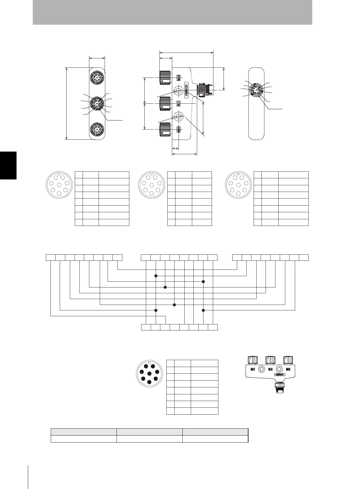
4-Joint Plug/Socket Connector for Receiver (F39-GCN4-D, black, sold separately)
<Internal wiring diagram>
Set model name Emitter Receiver
F39-GCN4 F39-GCN4-L F39-GCN4-D
17
78
3
5
2
1
6
M12 x 1
5
8
7
2
3
M12 x 1
7
27
58.3
13.6
MA2
SLC
MA1
CN
28
28 28
24.4
2-dia. 5.5
2-dia.10
4
7
8
6
1
4
MA1
Connected to Power Cable or
Double-Ended Cable of F3SG-RA Receiver
Connected to Single-Ended Cable or
Double-Ended Cable for Receiver
Connected to Power Cable or
Double-Ended Cable of F3W-MA Receiver
Connected to Power Cable or
Double-Ended Cable of F3W-MA Receiver
SLC MA2
CN
5
8
4
3
2
1
7
6
Female
5
8
6
7
1
2
3
4
Male
Yellow
Brown
Gray
Pink
Black
White
Blue
Red
Muting Enable
+24 VDC
COM+
COM-
Muting Output A
Muting Output B
0 VDC
CFG Out
1
2
3
4
5
6
7
8
5
8
4
3
2
1
7
6
Female
Yellow
Brown
Gray
Pink
Black
White
Blue
Red
RESET
+24 VDC
MUTE A
MUTE B
OSSD 1
OSSD 2
0 VDC
AUX
1
2
3
4
5
6
7
8
5
8
4
3
2
1
7
6
Female
Yellow
Brown
Gray
Pink
Black
White
Blue
Red
CFG In
+24 VDC
COM+
COM-
Muting Output A
Muting Output B
0 VDC
CFG Out
1
2
3
4
5
6
7
8
RESET
+24 VDC
Muting Enable
Not used
OSSD 1
OSSD 2
0 VDC
AUX
1
2
3
4
5
6
7
8
12345678 12345678
12345678
1234 5678
Yellow
Brown
Gray
Pink
Black
White
Blue
Red

 Loading...


