49
F3SG-R
User’s Manual
Chapter2 Muting
System Operation and Functions
E
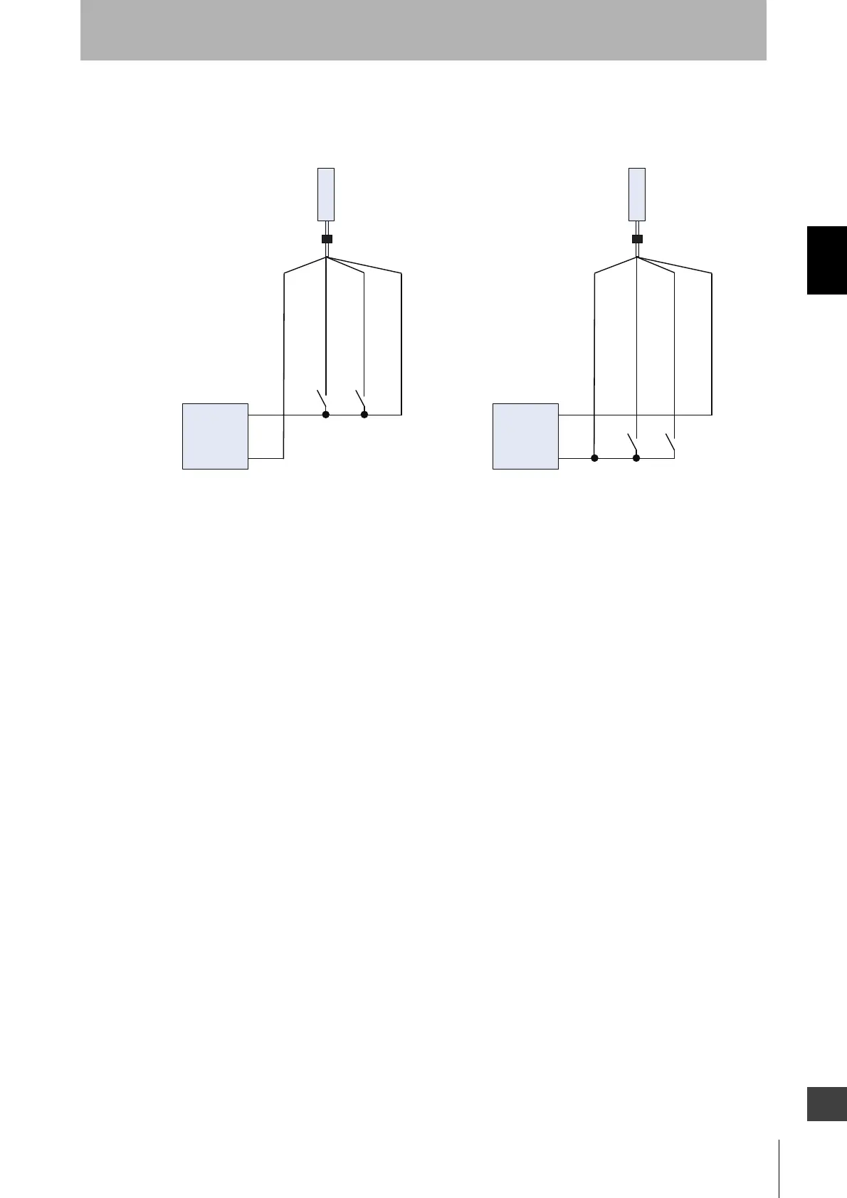
Wiring diagram
Installation standard for muting sensors
• Set the muting sensors so that they can detect all of the passing detection (palettes, automobiles,
etc.). Do not install the muting sensor in a position so that only the front or rear end of the objects is
detected.
• Set the muting sensors so that they detect the objects even when they are loaded on palettes or
other transport devices.
• Also, install the F3SG-R and muting sensors so that each object passes through all muting sensors
before the next object arrives at the first muting sensor. Also, install all F3SG-Rs and muting sensors
so that no person is able to accidentally enter the hazardous zone while the muting function is
enabled.
• If objects' speeds can vary, the allocation of muting sensors must be taken into consideration.
• Install muting sensors so that they can distinguish between the object that is being allowed to be
passed through the detection zone and a person.
MUTE A : Gray
MUTE B : Pink
MUTE A : Gray
MUTE B : Pink
S1 S2
S1 S2
S1, S2:
Muting sensor
F39-JGA-D F39-JGA-D
S1, S2:
Muting sensor
PNP output NPN output
Receiver
Receiver
Power supply
0 VDC : Blue
24 VDC : Brown
0 VDC : Blue
24 VDC : Brown
0 VDC
+24 VDC
Power supply
0 VDC
+24 VDC

 Loading...


