65
F3SG-R
User’s Manual
Chapter2 Muting
System Operation and Functions
E
Wiring diagram
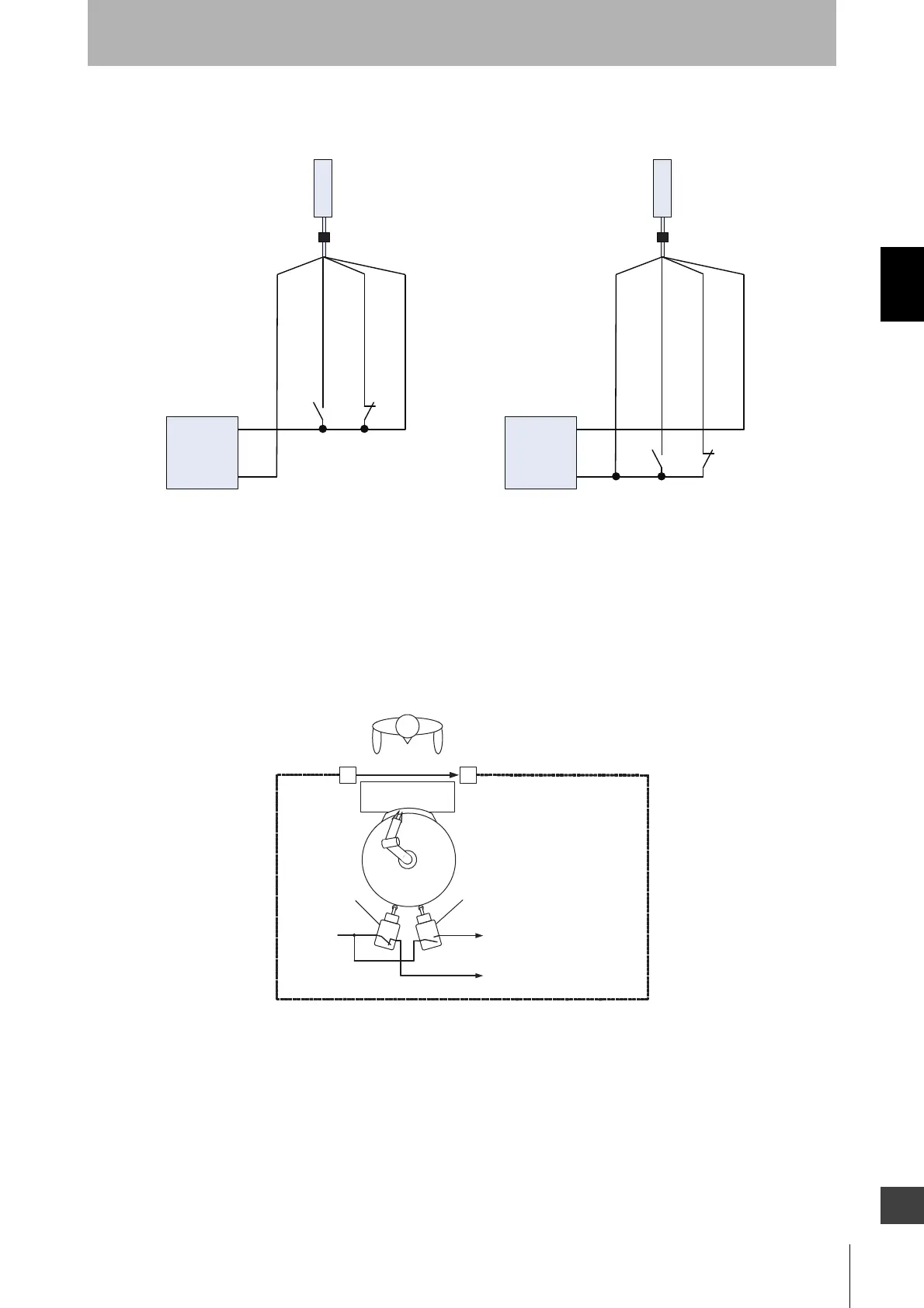
Installation Example of Position Detection Muting Mode
Shown below is an installation example of position detection muting mode.
This is an application that places a workpiece on a machine’s turntable surrounded by guard fence.
When hazardous part of the machine is on the opposite side of a human body, safety function of
F3SG-RA can be disabled so that an operator should be able to place a workpiece on the turntable.
1. Hazardous part of the machine is on the same side of a human body
The safety functions of the F3SG-RA is activated with the limit switch 1 being in the OFF state and the
limit switch 2 in the ON state.
S1
S1
㻿㻞
㻿㻞
MUTE A : Gray
MUTE B : Pink
MUTE A : Gray
MUTE B : Pink
S1, S2:
Muting sensor
F39-JGA-D F39-JGA-D
S1, S2:
Muting sensor
PNP output NPN output
Receiver
Receiver
Power supply
0 VDC : Blue
0 VDC : Blue
24 VDC : Brown
24 VDC : Brown
0 VDC
+24 VDC
Power supply
0 VDC
+24 VDC
Under normal operation
Guard fence
F3SG-RA
24 V or 0 V
Worktable
Robot arm
table
OFF: To muting input A
ON: To muting input B
Limit switch1
(N.O. Contact)
Limit switch 2
(N.C. Contact)

 Loading...


