WWW.NNC.IR
Macro Reference
649
8
Appendices
Vision System FH/FZ5 Series
User’s Manual (Z340)
ReadPlcMemory
Reads a value from the PLC memory area.
Format
ReadPlcMemory <ioIdent>, <area>, <channelOffset>, <channelCount>, <readData()>
Parameter
Return value
None.
Description
Using the communication module specified in the <ioIdent> parameter, the data size specified in the
<channelCount> parameter is read from the address that is offset by the value specified in the
<channelOffset> parameter, of the PLC area type specified in the <area> parameter.
After reading the value from the PLC memory area using this macro function, execute the GetPlcData
function to get the read value.
In the <readData()> parameter, specify the 1D integer array variable that stores the data that was read. Add
() without specifying element numbers.
This macro function cannot be used to read data from a PLC that is connected by other than the PLC link
communication module.
In the <area> parameter, specify the Identification of the register that is set with the PLC link setting in the
system settings.
In the <channelCount> parameter, specify the size in channel units. The size of one integer type data item is
two channels (four bytes), and thus to read one integer value, a one-element array should be prepared with
the <readData()> parameter, and 2 should be specified in the <channelCount> parameter.
If a size larger than the array size specified in the <readData()> parameter is specified in the <channelCount>
parameter, a "Subscript out of range" error will occur.
If an incorrect data type is specified for a parameter, a "Type mismatch" error will occur.
If a non-existent number, numerical value, or combination of data types or values is specified for a parameter,
an "Illegal function call" error will occur.
If the format is written incorrectly, such as writing the macro function name incorrectly, omitting a comma, or
omitting a half-width space, a "Syntax error" error will occur.
Usage Cautions
• After using this macro function to read data, always use the GetPlcData function to get the value from the
data that was read. If the value is gotten directly from the <readData()> parameter without using the
GetPlcData function, the correct value may not be gotten.
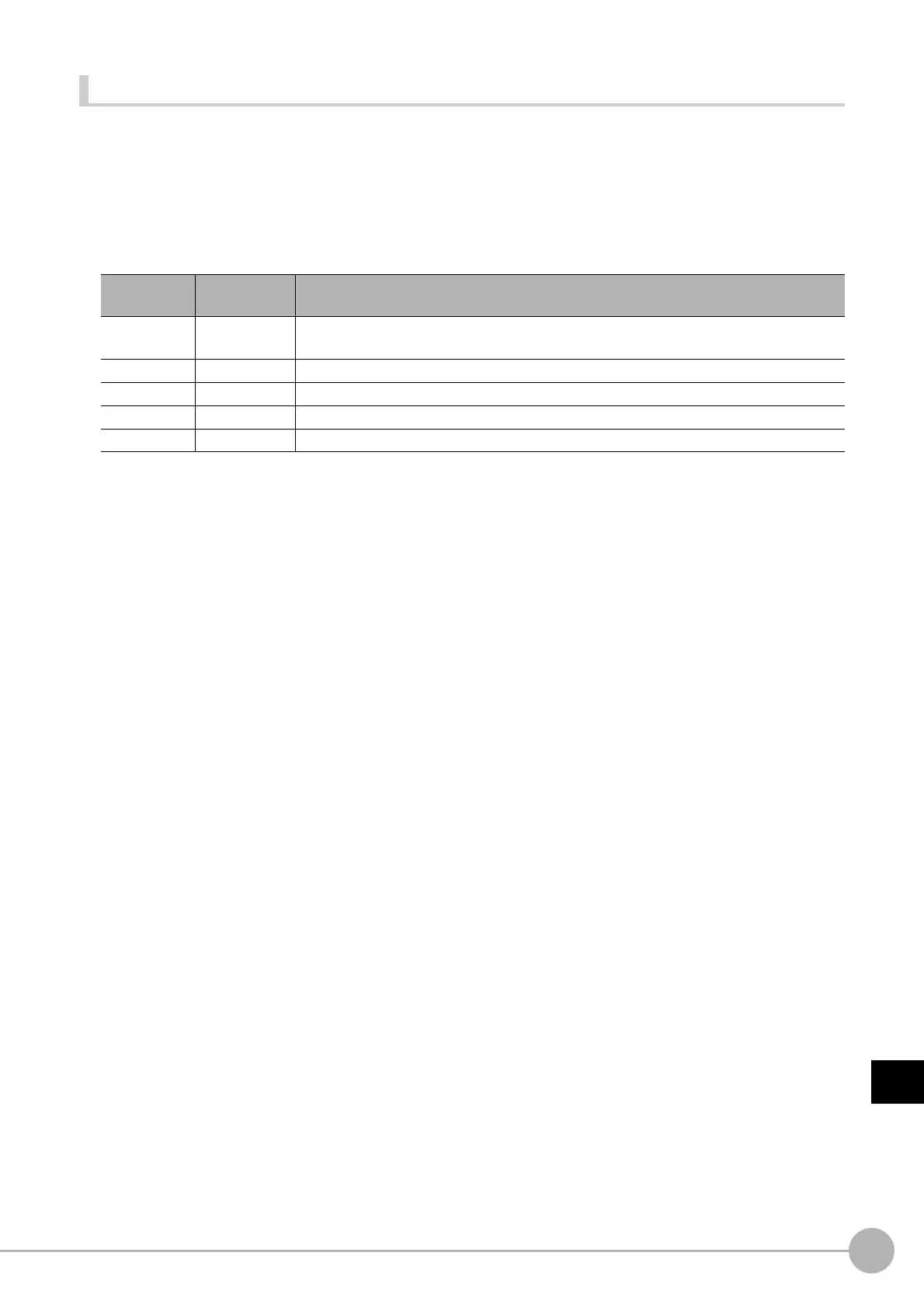
Parameter
name
Data type Description
<ioIdent>
Character
string type
Identification name of the communication module to be used (Reference: XList of I/O
Modules (p.341))
<area> Integer type Area classification number of data output area to read in the target
<channelOffset>
Integer type Offset from beginning of data output area to address where reading is to start.
<channelCount>
Integer type Data size to read in (channel unit)
<readData()> Integer array Loaded data

 Loading...

