WWW.NNC.IR
Alignment
302
Vision System FH/FZ5 Series
User’s Manual (Z340)
Alignment
An FH/FZ5-series Controller has an alignment function that you can use to position workpieces for stage and
robot applications (hereafter called external devices).
Alignment executes a combination of more than one processing item.
This section gives an overview of alignment, and provides details on its use in general.
Refer to the Vision System FH/FZ5 Series Processing Item Function Reference Manual (Cat No. Z341) for
details on the processing items that are used for alignment.
Overview
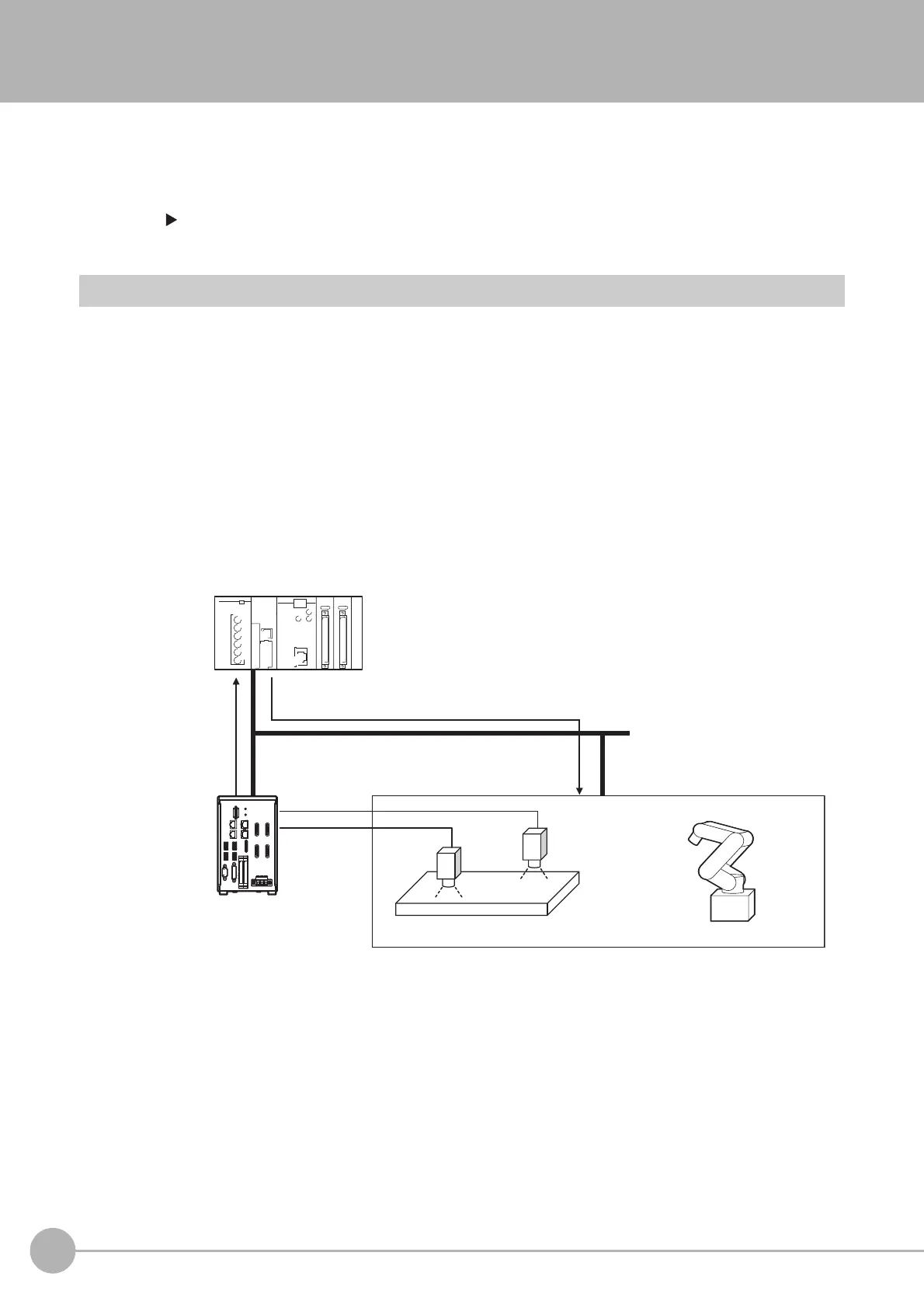
An FH/FZ5-series Controller measures the position of alignment marks on the workpiece, or the position of
specific features of the workpiece (such as corners), and outputs the axis movement to a PLC or stage
controller, which aligns the workpiece into a specified position (hereafter called the reference position).
The PLC or stage controller simply needs to send a movement command to the external device for the axis
movement amount that was output from the FH/FZ5-series Controller to align the position of the workpiece.
The following two measurement flows are used to perform alignment. Set both flows for each scene.
• Calibration flow
This flow associates the coordinates of the external device with the Camera coordinates.
• Alignment flow
This flow uses the calibration parameters that were created in the calibration flow to align the position of the
workpiece.
PLC
Sensor Controller
Stage Robot
Or
Movement command (stage or robot coordinates)
Required move-
ment (stage or
robot coordinates)
Conversion of stage or
robot coordinations from
Camera coordinates

 Loading...

